CDB35L00 Cirrus Logic Inc, CDB35L00 Datasheet - Page 3
CDB35L00
Manufacturer Part Number
CDB35L00
Description
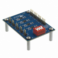
DEVELOPMENT BOARD FOR CS35L0X
Manufacturer
Cirrus Logic Inc
Datasheet
1.CDB35L00.pdf
(12 pages)
Specifications of CDB35L00
Amplifier Type
Class D
Output Type
4-Channel (Quad)
Max Output Power X Channels @ Load
2.7W x 4 @ 4 Ohm
Voltage - Supply
2.5 V ~ 5.5 V
Board Type
Fully Populated
Utilized Ic / Part
CS35L0X
Description/function
Audio Amplifiers
Operating Supply Voltage
2.5 V to 5.5 V
Output Power
1.6 W, 2.7 W
Product
Audio Modules
For Use With/related Products
CS35L00
Lead Free Status / RoHS Status
Contains lead / RoHS non-compliant
Operating Temperature
-
Lead Free Status / Rohs Status
Lead free / RoHS Compliant
Other names
598-1803


DS913DB2
1. SYSTEM OVERVIEW
The CDB35L00-X4 demonstration board is an practical means for evaluating the CS35L00 2.7 W Hybrid Class-D
amplifier with low idle current consumption. A differential mono analog input signal interface is provided for each
device. Optional input gain and output filtering component placeholders are provided for easy modification to custom
tune the CS35L00 for the user’s specific system requirements.
1.1
1.2
1.3
1.3.1
CS35L00 Hybrid Class-D Amplifier
The CS35L00 Hybrid Class-D amplifier is a 2.7 W mono, full-bridge, closed-loop, audio amplifier available
in a 10-pin, 3 mm x 3 mm, DFN package. A complete description of the CS35L00 is included in the CS35L00
product data sheet.
Power Supply
A single +2.5 to +5.5 VDC power supply is required to power the CDB35L00-X4. The supply must be capa-
ble of delivering sufficient current for the intended power output. The supply provides power to each of the
four CS35L00 amplifiers. The power supply connection to the board is provided by the header J1. The pos-
itive terminal is labeled VBATT. The ground terminal is labeled GND.
Operational Modes
The CS35L00 device has 4 different operational modes. Each of the 4 operational modes requires different
board configuration as described in
CS35L00 are listed below. More information on the specifics of each operational mode can be found in the
CS35L00 product datasheet.
•
•
•
•
The CDB35L00-X4 demonstration board schematic is shown in
Operational Mode Control
Using a combination of the S1 switch and the hybrid control resistors, as described in
allows the CDB35L00-X4 to be configured in all 4 of the operational modes listed in
Each CS35L00’s MODE pin on the CDB35L00-X4
board is connected to the S1 switch labeled MODE as
shown in
whether all four of the CS35L00 devices on the
CDB35L00-X4 board are operating in one of the re-
duced frequency modes (FSD or FHD) or in one of the
higher frequency modes (SD or HD).
Table 1 on page 3
CDB35L00-X4 board. More configuration options are available by removing or repopulating 0 resistors
as described in
Note:
S1 switch or by removing power when the operational mode is being changed.
SD: Standard Class-D Mode
FSD: Reduced Frequency Standard Class-D Mode
HD: Hybrid Class-D Mode
FHD: Reduced Frequency Hybrid Class-D Mode
In order to avoid transient audio signals, the CS35L00 devices should be shutdown either via the
Figure 4 on page
Section
and
1.4.
Table 3 on page 5
9. The MODE pin controls
Section 1.3.1
show the S1 switch-controlled configuration options on the
and
Section
Figure 4 on page
HIGH
LOW
1.3.1.1. The operational modes of the
Table 1. S1 Switch GAIN & MODE
Configurations
+12 dB
+6 dB
GAIN
9.
CDB35L00-X4
Section
Section
FSD / FHD
SD / HD
MODE
1.3.
1.3.1.1,
3
Related parts for CDB35L00
Image
Part Number
Description
Manufacturer
Datasheet
Request
R

Part Number:
Description:
Audio Modules & Development Tools Eval Bd - DF 4ch ADC 8ch DAC & 32bit DSP
Manufacturer:
Cirrus Logic Inc
Part Number:
Description:
Development Kit
Manufacturer:
Cirrus Logic Inc
Datasheet:
Part Number:
Description:
Development Kit
Manufacturer:
Cirrus Logic Inc
Datasheet:


Part Number:
Description:
High-efficiency PFC + Fluorescent Lamp Driver Reference Design
Manufacturer:
Cirrus Logic Inc
Datasheet:
Part Number:
Description:
Development Kit
Manufacturer:
Cirrus Logic Inc
Datasheet:
Part Number:
Description:
Development Kit
Manufacturer:
Cirrus Logic Inc
Datasheet:

Part Number:
Description:
Development Kit
Manufacturer:
Cirrus Logic Inc
Datasheet:
Part Number:
Description:
Development Kit
Manufacturer:
Cirrus Logic Inc
Datasheet:
Part Number:
Description:
Development Kit
Manufacturer:
Cirrus Logic Inc
Datasheet:

Part Number:
Description:
EVALUATION BOARD FOR CS8427
Manufacturer:
Cirrus Logic Inc
Datasheet:

Part Number:
Description:
BOARD EVAL FOR CS8416 RCVR
Manufacturer:
Cirrus Logic Inc
Datasheet:

Part Number:
Description:
EVALUATION BOARD FOR CS8420
Manufacturer:
Cirrus Logic Inc
Datasheet:

Part Number:
Description:
KIT DEVELOPMENT EP9315 ARM9
Manufacturer:
Cirrus Logic Inc
Datasheet:

Part Number:
Description:
KIT DEVELOPMENT EP9302 ARM9
Manufacturer:
Cirrus Logic Inc
Datasheet: