CDB35L00 Cirrus Logic Inc, CDB35L00 Datasheet - Page 4
CDB35L00
Manufacturer Part Number
CDB35L00
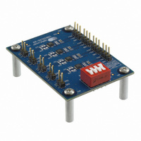
Description
DEVELOPMENT BOARD FOR CS35L0X
Manufacturer
Cirrus Logic Inc
Datasheet
1.CDB35L00.pdf
(12 pages)
Specifications of CDB35L00
Amplifier Type
Class D
Output Type
4-Channel (Quad)
Max Output Power X Channels @ Load
2.7W x 4 @ 4 Ohm
Voltage - Supply
2.5 V ~ 5.5 V
Board Type
Fully Populated
Utilized Ic / Part
CS35L0X
Description/function
Audio Amplifiers
Operating Supply Voltage
2.5 V to 5.5 V
Output Power
1.6 W, 2.7 W
Product
Audio Modules
For Use With/related Products
CS35L00
Lead Free Status / RoHS Status
Contains lead / RoHS non-compliant
Operating Temperature
-
Lead Free Status / Rohs Status
Lead free / RoHS Compliant
Other names
598-1803


4
1.4
Shutdown Control
The S1 switch implements shutdown control for the four CS35L00 devices on the CDB35L00-X4. SD1-2
controls the shutdown for U1 and U2. SD3-4 controls the shutdown for U3 and U4 as shown in
on the schematic in
1.3.1.1
Each CS35L00 device has a hybrid control resistor. When
the hybrid control resistor for each CS35L00 is populated,
it connects the LFILT+ pin to VBATT and enables the
Standard Class-D functionality (SD or FSD modes) for the
corresponding device. When the hybrid control resistor
for each CS35L00 is not populated, LFILT+ is floating,
and the Hybrid Class-D functionality (HD or FHD modes)
is enabled.
The hybrid control resistors (R13, R23, R33, R43) are lo-
cated on the bottom side of the board adjacent to the
LFILT+ decoupling capacitor and are highlighted in blue
in
A combination of the hybrid control resistors and the S1
MODE switch allow the CS35L00 devices (U1-U4) on the
CDB35L00-X4 board to be configured in all 4 of the oper-
ational modes. There is no requirement to have the all
four of the CS35L00 devices configured in the same
mode. Each device can be configured to the user’s re-
quirements.
able using the hybrid control resistors and the S1 MODE
switch.
Figure
1.
Hybrid Control Resistor Configuration
Table 2
Table 2. Hybrid Control Resistor & S1 Switch MODE Configurations
Figure 4 on page
lists the configuration options avail-
R13: Removed
R23: Removed
R33: Removed
R43: Removed
R13: VBATT
R23: VBATT
R33: VBATT
R43: VBATT
9.
U1 = FSD
U1 = FHD
U2 = FSD
U2 = FHD
U3 = FSD
U3 = FHD
U4 = FSD
U4 = FHD
GND
S1 MODE Switch:
Figure 1. Hybrid Control Resistors
U1 = SD
U1 = HD
U2 = SD
U2 = HD
U3 = SD
U3 = HD
U4 = SD
U4 = HD
VBATT
CDB35L00-X4
DS913DB2
Table 3
and
Related parts for CDB35L00
Image
Part Number
Description
Manufacturer
Datasheet
Request
R

Part Number:
Description:
Audio Modules & Development Tools Eval Bd - DF 4ch ADC 8ch DAC & 32bit DSP
Manufacturer:
Cirrus Logic Inc
Part Number:
Description:
Development Kit
Manufacturer:
Cirrus Logic Inc
Datasheet:
Part Number:
Description:
Development Kit
Manufacturer:
Cirrus Logic Inc
Datasheet:


Part Number:
Description:
High-efficiency PFC + Fluorescent Lamp Driver Reference Design
Manufacturer:
Cirrus Logic Inc
Datasheet:
Part Number:
Description:
Development Kit
Manufacturer:
Cirrus Logic Inc
Datasheet:
Part Number:
Description:
Development Kit
Manufacturer:
Cirrus Logic Inc
Datasheet:

Part Number:
Description:
Development Kit
Manufacturer:
Cirrus Logic Inc
Datasheet:
Part Number:
Description:
Development Kit
Manufacturer:
Cirrus Logic Inc
Datasheet:
Part Number:
Description:
Development Kit
Manufacturer:
Cirrus Logic Inc
Datasheet:

Part Number:
Description:
EVALUATION BOARD FOR CS8427
Manufacturer:
Cirrus Logic Inc
Datasheet:

Part Number:
Description:
BOARD EVAL FOR CS8416 RCVR
Manufacturer:
Cirrus Logic Inc
Datasheet:

Part Number:
Description:
EVALUATION BOARD FOR CS8420
Manufacturer:
Cirrus Logic Inc
Datasheet:

Part Number:
Description:
KIT DEVELOPMENT EP9315 ARM9
Manufacturer:
Cirrus Logic Inc
Datasheet:

Part Number:
Description:
KIT DEVELOPMENT EP9302 ARM9
Manufacturer:
Cirrus Logic Inc
Datasheet: