MCP1640EV-SBC Microchip Technology, MCP1640EV-SBC Datasheet - Page 12
MCP1640EV-SBC
Manufacturer Part Number
MCP1640EV-SBC
Description
BOARD EVAL FOR MCP1640
Manufacturer
Microchip Technology
Type
DC/DC Switching Converters, Regulators & Controllersr
Datasheets
1.MCP1640CT-ICHY.pdf
(32 pages)
2.MCP1640CT-ICHY.pdf
(26 pages)
3.MCP1640EV-SBC.pdf
(22 pages)
Specifications of MCP1640EV-SBC
Main Purpose
DC/DC, Step Up
Outputs And Type
1, Non-Isolated
Voltage - Output
2V, 3.3V or 5V
Current - Output
100mA, 350mA
Voltage - Input
0.35 ~ 5.5V
Regulator Topology
Boost
Frequency - Switching
500kHz
Board Type
Fully Populated
Utilized Ic / Part
MCP1640
Input Voltage
0.35 V to 5.5 V
Output Voltage
3.3 V to 5 V
Operating Supply Voltage
0.35 V to 5.5 V
Product
Power Management Modules
Supply Current
300 mA
Kit Contents
Board
Features
Automatic PFM/PWM Operation, Enable State Selectable Using Mini-Dip Switch On Board
Svhc
No SVHC (15-Dec-2010)
Core Architecture
Power Management - Voltage Regulator
Rohs Compliant
Yes
For Use With/related Products
MCP1640
Lead Free Status / RoHS Status
Contains lead / RoHS non-compliant
Power - Output
-
Lead Free Status / Rohs Status
Lead free / RoHS Compliant
Available stocks
Company
Part Number
Manufacturer
Quantity
Price
Company:

Part Number:
MCP1640EV-SBC
Manufacturer:
Microchip Technology
Quantity:
135
Company:
Part Number:
MCP1640EV-SBC
Manufacturer:
MICROCHIP
Quantity:
12 000


MCP1640 Synchronous Boost Converter Evaluation Board User’s Guide
2.2
2.3
DS51880A-page 12
FEATURES
GETTING STARTED
The MCP1640 Evaluation Board offers both package types in two boost-converter
applications for 2.0V, 3.3V and 5.0V output voltage options that can be selected using
a mini dip switch. The enable input is controlled in both boost converter applications
using a mini dip switch.
The MCP1640 Synchronous Boost Converter Evaluation Board has the following
features:
• It can be powered by one-cell, two-cell, or three-cell alkaline, NiCd, NiMH,
• Input voltage range, V
• Fixed output voltage: 2.0V or 3.3V and 3.3V or 5.0V, selected using a mini dip
• Output current: typical 100 mA @ 3.3V Output, 1.2V Input or 300 mA @ 5.0V
• Start-up voltage: 0.65V at V
• Automatic PFM/PWM Operation
• PWM Switching Frequency = 500 kHz
• Enable state selectable using mini-dip switch on board
• Peak Input Current Limit
• Overtemperature (if the die temperature exceeds 150°C, 10°C hysteresis)
The MCP1640 Synchronous Boost Converter Evaluation Board is fully assembled and
tested to evaluate and demonstrate the MCP1640 products. This board requires the
use of external lab supplies and load.
2.3.1
2.3.1.1
Soldered test points are available for input voltage connections. The maximum input
voltage should not exceed 6.0V. The output voltage will not remain in regulation for
input voltages that are greater than or equal to the output voltage.
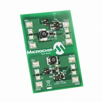
The MC1640 Synchronous Boost Converter Evaluation Board has two independent
circuit applications, one using the MCP1640 SOT-23-6 package, while the other one
uses the MCP1640 DFN-8 package. The SOT-23-6 package has two output voltage
settings (2.0V and 3.3V) selectable by an on board mini-dip switch. The DFN-8
package has two output voltage settings (3.3V and 5.0V) also selectable by an on
board mini-dip switch.
Soldered test points are available to connect a load. The MCP1640 switch peak current
limit will provide a safe maximum current value. The maximum output current for the
MCP1640 will vary with input and output voltages; refer to the MCP1640 datasheet for
more information on the maximum output current. As an example, the MCP1640 can
typically supply a 3.3V load with 100 mA with a 1.2V input.
one-cell Li-Ion or Li-Polymer batteries
switch on board
Output, 3.3V Input
Power Input and Output Connection
EVALUATION BOARD
POWERING THE MCP1640 SYNCHRONOUS BOOST CONVERTER
IN
: 0.35V to 5.5V, with V
IN
= 1.2V, V
OUT
= 3.3V and I
IN
V
OUT
; 1 mA load after startup
OUT
2010 Microchip Technology Inc.
= 1mA, resistive load
Related parts for MCP1640EV-SBC
Image
Part Number
Description
Manufacturer
Datasheet
Request
R

Part Number:
Description:
0.65V Start-up Synchronous Boost Regulator with True Output Disconnect or Input/Output Bypass Option
Manufacturer:
MICROCHIP [Microchip Technology]
Datasheet:

Part Number:
Description:
IC CONV DC-DC STEPUP SYNC 8DFN
Manufacturer:
Microchip Technology
Datasheet:

Part Number:
Description:
0.65v Start-up Synchronous Boost Regulator With True Output Disconnect Or Input/output Bypass Option
Manufacturer:
Microchip Technology Inc.
Datasheet:
Part Number:
Description:
Manufacturer:
Microchip Technology Inc.
Datasheet:
Part Number:
Description:
Manufacturer:
Microchip Technology Inc.
Datasheet:
Part Number:
Description:
Manufacturer:
Microchip Technology Inc.
Datasheet:
Part Number:
Description:
Manufacturer:
Microchip Technology Inc.
Datasheet:
Part Number:
Description:
Manufacturer:
Microchip Technology Inc.
Datasheet:
Part Number:
Description:
Manufacturer:
Microchip Technology Inc.
Datasheet:
Part Number:
Description:
Manufacturer:
Microchip Technology Inc.
Datasheet: