SI3452MS8-KIT Silicon Laboratories Inc, SI3452MS8-KIT Datasheet
SI3452MS8-KIT
Specifications of SI3452MS8-KIT


Related parts for SI3452MS8-KIT

SI3452MS8-KIT Summary of contents
Page 1
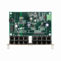
... VALUATION 1. Introduction The Si3452MS8 8-port evaluation kit (Si3452MS8-KIT) is intended for Power over Ethernet (PoE) Power Sourcing Equipment (PSE) system designers interested in evaluating the Quad-port Si3452 PSE controller. While evaluation kits are normally shipped with Si3452 devices that use Silicon Laboratories’ proprietary dV/dt™ disconnect, they can also be used for evaluation of the pin-compatible Si3453, which uses dc disconnect. In this case, the Si3452 devices must be replaced with the appropriate Si3453 device. Please refer to " ...
Page 2
... Si3452MS8-KIT 2. Kit Contents This user’s guide includes instructions on the use of the Si3452 register control GUI. An optional Power Manager GUI is described in the SI3452 Power Manager GUI user’s guide on the CD-ROM. The installation instructions for 2 the hardware and USB driver in this user’s guide must be followed before installing and using the Si3452 Power Manager GUI ...
Page 3
... USB to SMBus adapter into any USB port. A New Hardware wizard will appear and ask whether Windows can connect to Windows Update to search for software. Select “No, not this time”, and click “Next”. Figure 1. New Hardware Wizard Screen Select “Install the software automatically (Recommended)”, and click “Next” to continue. Si3452MS8-KIT Rev. 0.5 3 ...
Page 4
... Si3452MS8-KIT Figure 2. Choose “Install The Software Automatically” After successfully finishing the driver installation, the yellow LED on the USB-I2C board will turn on. 4 Rev. 0.5 ...
Page 5
... Si3452 Monitor GUI Installation Right-click on “Si3452_I2C_Monitor_Setup.exe” in the “Software” directory of the CD ROM, and select “Run as administrator”. Accept the EVLA. It will start to install PC GUI (Si3452 I2C Monitor). Press “Next” to continue. 2 Figure Monitor Setup Wizard Rev. 0.5 Si3452MS8-KIT 5 ...
Page 6
... Si3452MS8-KIT Select the folder path where to install the GUI (the default location is recommended) and press “Next”. Figure 4. I After successful installation, the program can be run from the installation directory or from the Start menu (StartAll ProgramsSilicon LaboratoriesSi3452 I2C Monitor). ...
Page 7
... Hardware installation Figures 5 and 6 show how all the hardware pieces of the Si3452 evaluation board fit together. Figure 6. Connection to Supply Power to the Isolated Side from the USB Adapter Figure 5. Evaluation Board Hardware Rev. 0.5 Si3452MS8-KIT 7 ...
Page 8
... Si3452MS8-KIT Perform the following steps: 1. Connect the Si3452 evaluation card (Si3452MB8-EVB) to the RJ45 (Si3452C3-EVB) card using the 24-pin ribbon cable. 2. The power should be applied before the USB-SMBus adapter is plugged in. The high-voltage power supply should be connected to the evaluation system before it is plugged into the ac mains. Hot insertion of the high voltage is not recommended ...
Page 9
... When the GUI is first started, the screen will look like the one shown in Figure 9. Pressing “Start Poll” and “Advanced” should yield a screen like the one shown in Figure 10 registers as described in the Si3452 data sheet. Normally, Figure 9. GUI Start-Up Screen Rev. 0.5 Si3452MS8-KIT 9 ...
Page 10
... Si3452MS8-KIT Figure 10. GUI Screen after Clicking “Advanced” and “Start Poll” If the power-up order was not followed possible that the Si3452 will not be recognized, in which case the firmware revision and Vee will show as 0.0.0 and 0 mV. In this case, close the GUI using the task manager if required ...
Page 11
... If the GUI is not in polling mode, clicking the “refresh” button reads these registers once. F. These panes show the status and basic configuration of each port and allow basic port control transmit address to 0x20 or 0x21. In the screen shot address that the GUI uses to communicate with Rev. 0.5 Si3452MS8-KIT ...
Page 12
... Si3452MS8-KIT GUI Display Detect The lower three bits of the port status registers are the detection status bits. These bits are decoded and displayed as the detect status. Detection status indicates the result of powered device (PD) detection detection has not been done, the result is “unknown”. Other possi- ble results are “ ...
Page 13
... Si3401 PD is plugged in, the cut-off current is automatically set to 643 mA. The screen shot in Figure 12 shows the result of plugging in a class 4 PD (into Port1) with 2x power enabled. Figure 12. Result of Putting Port 1 into Auto and POE+ Mode and Plugging in the Si3401 Class 4 PD with a 10 Load Si3452MS8-KIT Rev. 0.5 13 ...
Page 14
... Si3452MS8-KIT 7. Board Schematics, BOM, and Layout The following are general PCB layout considerations. Detailed schematics, BOM, and layout can also be found in the following sections. Visit the Silicon Labs Technical Support web page and register to submit a technical support request, particularly if you are not closely following the recommended reference design. ...
Page 15
... Si3452 Schematics +3V3 -52V +3V3 +3V3 -52V_RTN +3V3_RTN +3V3 VDD1 GND1 1 8 ISOLATION ISOLATION VDD2 GND2 16 9 Si3452MS8-KIT +3V3 +3V3 -52V -52V -52V Rev. 0.5 -52V 15 ...
Page 16
... Si3452MS8-KIT +3V3 +3V3 EPAD VSS2 19 SWO 18 VSS1 17 Vposs +3V3 16 Vssa R153 R153 NC 5 RDET 6 HSO Vneg -52V Rev. 0.5 ...
Page 17
... R8 10K 10K R7 R7 10K R6 10K R6 10K R5 10K R5 VDD 30 +3V3 VDD 19 -52V 10K R4 10K R4 10K R3 10K R3 10K 10K R2 R2 10K 10K R1 R1 Si3452MS8-KIT -52V GND12 35 GND34 15 VEE -52V 2 VEE EPAD AGND 8 DGND 29 -52V GND12 35 GND34 15 VEE -52V 2 VEE EPAD AGND 8 DGND 29 Rev. 0.5 ...
Page 18
... Si3452MS8-KIT 7.3. Si3452 Layout 18 Rev. 0.5 ...
Page 19
... Si3452MS8-KIT Rev. 0.5 19 ...
Page 20
... Si3452MS8-KIT 20 Rev. 0.5 ...
Page 21
... Si3452MS8-KIT Rev. 0.5 21 ...
Page 22
... Si3452MS8-KIT 22 Rev. 0.5 ...
Page 23
... SMT LED-0805-K 2.2 V 2.0 A, Single DO-214AA 100 V 1000 mA SMT L0603 Header CONN-2X12-2MM Socket CONN2X3-FRA Term Blk CONN-TB-1757242 Male Rev. 0.5 Si3452MS8-KIT Manufacturer Part Manufacturer Number C0603X7R160-104M Venkel C0603X7R101-104M Venkel C0805X7R160-105M Venkel GA342QR7GD681K Murata W01L ECA2AM330 Panasonic C0603X5R6R3-106M Venkel EEUFC2A120 Panasonic ...
Page 24
... Si3452MS8-KIT Table 2. Si3452 Bill of Materials (Continued) Item Qty Reference Value 23 1 J104 HEADER 5x2 24 1 L151 33 µ MMBT3904 26 9 R1,R2,R3,R4, 10 k R5,R6,R7,R8, R157 27 3 R9,R10,R104 44.2 k R100,R103 10 k R101,R102, 1 k R153* 330 R105 267 R106,R107 ...
Page 25
... RJ45 Connector Board Schematics Si3452MS8-KIT +3V3_RTN +3V3 +3V3 Rev. 0.5 25 ...
Page 26
... Si3452MS8-KIT 8 +3V3 Rev. 0.5 ...
Page 27
... Rev. 0.5 Si3452MS8-KIT ...
Page 28
... Si3452MS8-KIT 7.6. RJ45 Connector Board Layout 28 Rev. 0.5 ...
Page 29
... Si3452MS8-KIT Rev. 0.5 29 ...
Page 30
... Si3452MS8-KIT 30 Rev. 0.5 ...
Page 31
... Si3452MS8-KIT Rev. 0.5 31 ...
Page 32
... Si3452MS8-KIT 32 Rev. 0.5 ...
Page 33
... R0805 332 1/10 W ±1% R0603 1 k 1/16 W ±1% R0603 2.15 k 1/10 W ±1% R0603 714 mW SOT23-8N Rev. 0.5 Si3452MS8-KIT Mfr Part Number Mfr C0805X7R160-105M Venkel C1210X7R251-104M Venkel LTST-C170GKT LITE_ON INC TMM-112-01-T-D Samtec 44170-0001 MOLEX FA2536-ALD COIL- CRAFT CR0603-16W-1004F ...
Page 34
... Si3452MS8-KIT A — I PPENDIX NSTALLING Checking whether Driver is Installed To check whether the driver is installed, perform the following steps: 1. Open the Control Panel and click the System icon NINSTALLING Figure 29. Control Panel Rev. 0.5 ...
Page 35
... Select “Hardware” and click Device Manager. The screen shown in Figure 30 will appear. 3. Click on “Universal Serial Bus Controllers”, and has installed, it will appear as “USB-I2C bridge version 2”. Figure 30. Device Manager Rev. 0.5 Si3452MS8-KIT 35 ...
Page 36
... Si3452MS8-KIT Uninstalling the USB uninstall the USB driver, perform the following steps: 1. Open Control Panel and click the Add or Remove Programs icon. 2. Search “Silicon Labs USB to I2C” and click on Change/Remove button to uninstall the driver Driver Figure 31. Add/Remove Programs Rev. 0.5 ...
Page 37
... Uninstalling the Si3452 Monitor GUI To uninstall the Si3452 monitor GUI, select it from “Add/Remove Programs” in the Control Panel. Figure 32. Monitor Setup Wizard Rev. 0.5 Si3452MS8-KIT 37 ...
Page 38
... Due to the unique high-voltage and high-power design considerations, Silicon Labs recommends that the reference designs be followed closely. Visit the Silicon Labs Technical Support web page and register to submit a technical support request, particularly if you are not closely following the recommended reference design. Ordering Part Number Si3452MS8-KIT Si3452-XYY-GM 38 Description Evaluation board kit for Si3452, 8-port midspan evaluation board reference design ...
Page 39
... Changed document title from Si3452MS8-EVB to Si3452MS8-KIT. Updated "3. Software Installation" on page 3. Updated "3.1. USB to I2C Driver Installation" on page 3. Updated "3.2. Si3452 Monitor GUI Installation" on page 5. Updated Figure 3 on page 5. Updated " Uninstalling the Si3452 Monitor GUI" on page 37. Si3452MS8-KIT Rev. 0.5 39 ...
Page 40
... Si3452MS8-KIT C I ONTACT NFORMATION Silicon Laboratories Inc. 400 West Cesar Chavez Austin, TX 78701 Tel: 1+(512) 416-8500 Fax: 1+(512) 416-9669 Toll Free: 1+(877) 444-3032 Please visit the Silicon Labs Technical Support web page: https://www.silabs.com/support/pages/contacttechnicalsupport.aspx and register to submit a technical support request. The information in this document is believed to be accurate in all respects at the time of publication but is subject to change without notice. ...