NCP1271ADAPGEVB ON Semiconductor, NCP1271ADAPGEVB Datasheet
NCP1271ADAPGEVB
Manufacturer Part Number
NCP1271ADAPGEVB
Description
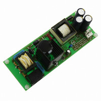
EVAL BOARD FOR NCP1271ADAPG
Manufacturer
ON Semiconductor
Datasheets
1.NCP1271P100G.pdf
(21 pages)
2.NCP1271ADAPGEVB.pdf
(1 pages)
3.NCP1271ADAPGEVB.pdf
(10 pages)
Specifications of NCP1271ADAPGEVB
Design Resources
NCP1271 Adapter EVB BOM NCP1271ADAPGEVB Gerber Files NCP1271EVB Schematic
Main Purpose
AC/DC, Primary Side
Outputs And Type
1, Isolated
Voltage - Output
19V
Current - Output
3A
Voltage - Input
85 ~ 265VAC
Regulator Topology
Flyback
Frequency - Switching
65kHz
Board Type
Fully Populated
Utilized Ic / Part
NCP1271
Silicon Manufacturer
On Semiconductor
Silicon Core Number
NCP1271
Kit Application Type
Power Management
Application Sub Type
PWM Controller
Peak Reflow Compatible (260 C)
No
Rohs Compliant
No
Lead Free Status / RoHS Status
Lead free / RoHS Compliant
Power - Output
-
Lead Free Status / Rohs Status
Lead free / RoHS Compliant
Other names
NCP1271ADAPGEVBOS
1/4/2007
Required Equipment
Test Procedure
* High Voltage is dangerous. Please be extra careful when dealing with high voltage.
1. >100VA 1-to-1 Isolated Transformer at AC line voltage
2. AC Power Supply with sinusoidal voltage output, 50 to 60 Hz, 85 to 264 Vac, at least 80 W
3. Digital Power Meter with low-power-range power consumption measurement capability
4. Oscilloscope or Voltmeter
5. NCP1271EVB Demo Board
6. Electronic Load that can handle at least 6.4 A 19 V 57 W
1. Connect the equipment as shown in the following figure.
2. The electronic load is will draw up to 3 A in constant current mode. Make sure that the wires connecting
3. Set the AC Power Supply to 85 Vac. Limit the maximum input current to 2 A.
4. Then, turn on the system and apply an 85 Vac input to the Demo Board with no load on the output.
5. Check if the output voltage is close to the nominal output 19 V and stable (no bouncing around). Note
6. Increase the load to 3A and check that the output voltage is 19 V.
7. Sweep the input voltage up to 264 Vac with 3A load on the output. Ensure that the output is 19 V and
8. Decrease the output load to 0.5 A and sweep the input voltage from 264 Vac to 85 Vac. Ensure that the
between the electronic load and demo board can handle 3 A current.
that there may be significant voltage drop across the output wire.
there is no noise.
output is 19 V and there is no noise.
Test Procedure for the NCP1271 (19 V 3 A) Evaluation Board
Related parts for NCP1271ADAPGEVB
Image
Part Number
Description
Manufacturer
Datasheet
Request
R

Part Number:
Description:
ON Semiconductor [VOLTAGE REGULATOR]
Manufacturer:
ON Semiconductor
Datasheet:
Part Number:
Description:
357-036-542-201 CARDEDGE 36POS DL .156 BLK LOPRO
Manufacturer:
ON Semiconductor
Datasheet:
Part Number:
Description:
357-036-542-201 CARDEDGE 36POS DL .156 BLK LOPRO
Manufacturer:
ON Semiconductor
Datasheet:
Part Number:
Description:
357-036-542-201 CARDEDGE 36POS DL .156 BLK LOPRO
Manufacturer:
ON Semiconductor
Datasheet:
Part Number:
Description:
357-036-542-201 CARDEDGE 36POS DL .156 BLK LOPRO
Manufacturer:
ON Semiconductor
Datasheet:
Part Number:
Description:
357-036-542-201 CARDEDGE 36POS DL .156 BLK LOPRO
Manufacturer:
ON Semiconductor
Datasheet:
Part Number:
Description:
357-036-542-201 CARDEDGE 36POS DL .156 BLK LOPRO
Manufacturer:
ON Semiconductor
Datasheet:
Part Number:
Description:
357-036-542-201 CARDEDGE 36POS DL .156 BLK LOPRO
Manufacturer:
ON Semiconductor
Datasheet:
Part Number:
Description:
357-036-542-201 CARDEDGE 36POS DL .156 BLK LOPRO
Manufacturer:
ON Semiconductor
Datasheet:
Part Number:
Description:
357-036-542-201 CARDEDGE 36POS DL .156 BLK LOPRO
Manufacturer:
ON Semiconductor
Datasheet:
Part Number:
Description:
357-036-542-201 CARDEDGE 36POS DL .156 BLK LOPRO
Manufacturer:
ON Semiconductor
Datasheet:
Part Number:
Description:
Manufacturer:
ON Semiconductor
Datasheet:
Part Number:
Description:
Manufacturer:
ON Semiconductor
Datasheet:
Part Number:
Description:
Manufacturer:
ON Semiconductor
Datasheet: