NCP1271ADAPGEVB ON Semiconductor, NCP1271ADAPGEVB Datasheet
NCP1271ADAPGEVB
Specifications of NCP1271ADAPGEVB


Related parts for NCP1271ADAPGEVB

NCP1271ADAPGEVB Summary of contents
Page 1
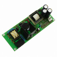
... AND8242 3.0 A Universal Input AC−DC Adaptor Using NCP1271 Prepared by: Kahou Wong ON Semiconductor INTRODUCTION This application note presents an example circuit in Figure 1 using NCP1271 (65 kHz version) in the flyback topology with the design steps and measurement. The measurement shows that the 19 V, 3.0 A circuit delivers above 85% from universal input (85 to 265 Vac) ...
Page 2
Table 1. Features of Power Supply Using NCP1271 Operation Mode Topology CCM/DCM Flyback Standby Condition Soft−Skip Operation Fault Condition Double Hiccup Restart Latch Protection Latched Off Activated Design Steps Step 1. Define the Specification Input 85 to 265 Vac, 50 ...
Page 3
The Continuous Conduction Mode (CCM) lossless flyback is with the following basic conversion equation. V out ) 1− the input voltage the output ...
Page 4
2−low−line + @ D V out ) 100 · 46.8% + 46.8% ( · 5 Hence, the DCM operation is confirmed here for < 100%. ...
Page 5
V . Hence, the optocoupler CC is connected to the V source that can be as high (±5%). In order to protect Pin 1, a 200 W is connected to limit ...
Page 6
Figure 7. Transient Response with R7 = 2.0 kW The maximum allowable duty is 80% when ramp resistor, R7, is smaller than 10 kW. Now that R7 = 511 W and the maximum allowable duty is 80% that covers the ...
Page 7
Measurement Part I. Standby Performance The circuit offers excellent no load standby performance. The 230−Vac power consumption of the 57 W circuit is 83 mW. When input is 230 Vac and output is 503 mW (19.13 V × 26.3 mA), ...
Page 8
Figure 11 shows a typical soft−skip pulse train during the standby operation. The yellow trace is the CS pin (Pin 3) voltage at 200 mV/div. The orange trace shows the duty that comes from 0% to 2.27%. The figure shows ...
Page 9
... Standoff M/F Hex 4−40 Nyl 0.750” 30F698 4−40 1/4 Inch Screw 31F2106 4−40 Screw Nuts http://onsemi.com 9 Manufacturer Coilcraft Cooper/Coiltronics ON Semiconductor ON Semiconductor Vishay ON Semiconductor ON Semiconductor ON Semiconductor ON Semiconductor ON Semiconductor ON Semiconductor ON Semiconductor Infineon Digi−key Yageo Vishay N/A Vishay Vishay Vishay Vishay Vishay Vishay Vishay Vishay Vishay ...
Page 10
... Fax: 480−829−7709 or 800−344−3867 Toll Free USA/Canada Email: orderlit@onsemi.com AND8242/D N. American Technical Support: 800−282−9855 Toll Free USA/Canada Japan: ON Semiconductor, Japan Customer Focus Center 2−9−1 Kamimeguro, Meguro−ku, Tokyo, Japan 153−0051 Phone: 81−3−5773−3850 http://onsemi.com 10 ON Semiconductor Website: http://onsemi ...