NCP1230GEVB ON Semiconductor, NCP1230GEVB Datasheet
NCP1230GEVB
Specifications of NCP1230GEVB


Related parts for NCP1230GEVB

NCP1230GEVB Summary of contents
Page 1
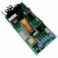
... AND8154/D NCP1230 90 Watt, Universal Input Adapter Power Supply Prepared by: Terry Allinder terry.allinder@onsemi.com ON Semiconductor General Description The NCP1230 implements a standard current mode control architecture. It’s an ideal candidate for applications where a low parts count is a key parameter, particularly in low cost adapter power supplies. The NCP1230 combines a ...
Page 2
... An Excel spreadsheet was designed using the above equation to help calculate the correct primary inductance value; visit the ON Semiconductor website for a copy of the spreadsheet. One method for calculating the transformer turns ratio is to minimize the voltage stress of the MOSFET (V the reflected output voltage. V DSmax + Vinmax ) n · ...
Page 3
... To limit the current into the Zener diode a 200 W resistor is placed between C5 and the Vcc pin (R28). ON Semiconductor recommends that the Vcc capacitor be at least sure that the Vcc supply voltage does not drop below Vccmin (7.6 V typical) during standby power mode and unusual fault conditions ...
Page 4
Where the output voltage Vf = the forward voltage drop across the output diode n is the transformer turns ratio 6. the transformer turns ratio The power dissipation in the clamp resistor is: ...
Page 5
Overtemperature Protection To implement Overtemperature Protection (OTP) shutdown, the Zener diode can be replaced by an NTC (refer to Figure 3 NTC can be placed in parallel with the Zener diode to have OVP and OTP protection. When ...
Page 6
... The first method was to use an Excel Spreadsheet (using the previously derived equations) which can be down loaded from the ON Semiconductor website (www://onsemi.com). The results from the Excel Spreadsheet are shown below. At full load and 200 Vdc (200 Vdc is the minimum voltage being supplied from the PFC) the loop gain crosses zero dB at approximately 1 ...
Page 7
NCP1230 OUT NCP1230 L = 0.22 mH averaged RI = 0.20 LoL Vin − 200 Vdc CoL 1 k ACMAG=1 Vstim FB C3 0.47 nF Figure 7. AC Frequency Response ...
Page 8
100 C22 C11 C27 0.1 0.47 0.22 4 100 mH L4 400 mH C17 D8 D9 0.1 mF ...
Page 9
R25 200 MMBT2907A/SOT PFC_Vcc GTS VCC 4 5 R26 GND DRV 10k NCP1230 C24 100pF C25 1.0 nF R24 R2 R29 R18 C6 0 0.01 mF 100k ...
Page 10
... Table 4. Standby Power Test Standby Power Pin Short Circuit Pin with 0.5 W Load Table 5. Vendor Contact List ON Semiconductor TDK Infineon Coilcraft Vishay Coiltronics Bussman (Cooper Ind.) Panasonic Weidmuller Keystone HH Smith Aavid Thermalloy AND8154 ...
Page 11
... Panasonic Vishay Panasonic Vishay Vishay Roederstein Vishay Roederstein Vishay Vishay Panasonic VISHAY Panasonic VISHAY Vishay Roederstein Vishay Vishay Vishay Vishay Roederstein Panasonic Vishay Vishay Vishay Roederstein VISHAY ON Semiconductor ON Semiconductor ON Semiconductor ON Semiconductor ON Semiconductor ON Semiconductor ON Semiconductor ON Semiconductor ON Semiconductor ON Semiconductor VISHAY VISHAY ON Semiconductor Bussman ...
Page 12
... TDK TDK Cooper Electronics Coilcraft Infineon Infineon ON Semiconductor VISHAY VISHAY VISHAY VISHAY VISHAY VISHAY VISHAY VISHAY VISHAY VISHAY VISHAY VISHAY VISHAY VISHAY VISHAY VISHAY VISHAY VISHAY VISHAY VISHAY VISHAY ON Semiconductor ON Semiconductor ON Semiconductor Infineon Cooper Electronics Digi−key Keystone Aavid Aavid Aavid ...
Page 13
Notes AND8154/D http://onsemi.com 13 ...
Page 14
... Fax: 480−829−7709 or 800−344−3867 Toll Free USA/Canada Email: orderlit@onsemi.com AND8154/D N. American Technical Support: 800−282−9855 Toll Free USA/Canada Japan: ON Semiconductor, Japan Customer Focus Center 2−9−1 Kamimeguro, Meguro−ku, Tokyo, Japan 153−0051 Phone: 81−3−5773−3850 http://onsemi.com 14 ON Semiconductor Website: http://onsemi ...