EVALSTSR30-60W STMicroelectronics, EVALSTSR30-60W Datasheet
EVALSTSR30-60W
Specifications of EVALSTSR30-60W
EVALSTSR30-60W
Available stocks


Related parts for EVALSTSR30-60W


EVALSTSR30-60W Summary of contents
Page 1
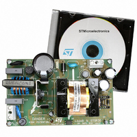
... PWM controller and the STSR30 smart driver for flyback synchronous rectification. This chipset guarantees low no-load consumption and high efficiency, making it easy to comply with world-wide mandatory and voluntary energy saving requirements. EVALSTSR30-60W demo board October 2006 EVALSTSR30-60W: 60W AC-DC Adapter Rev 2 AN2432 Application note www.st.com 1/27 ...
Page 2
AN2432 Contents 1 Adapter features . . . . . . . . . . . . . . . . . . . . . . . . . . . . . . . . . . . ...
Page 3
List of figures List of figures Figure 1. Electrical diagram . . . . . . . . . . . . . . . . . . . . . . . . . . . . . . ...
Page 4
AN2432 List of tables Table 1. Line and load regulation . . . . . . . . . . . . . . . . . . . . . . . . . . . . . . ...
Page 5
... This circuit implements a flyback transformer which is a very popular topology for this kind of application and power level, thanks to its simplicity and good trade-off between cost and performance. To improve the converter's efficiency, the EVALSTSR30 demo board uses synchronous rectification. The converter works in both Continuous and Discontinuous conduction mode depending on the input voltage (the circuit has a wide input voltage range) and the output load ...
Page 6
AN2432 Figure 1. Electrical diagram Adapter features 1 2 Vcc Gnd 8 4 GND 2 Vcc 5 DISABLE 6 PWRGND 4 OUTgate 2 1 GND VCC COMP 5 10 ...
Page 7
Adapter features The self supply circuit (Q2, R33, C23, L3, D6 and C6) ensures: ● a constant V ● enough energy during no-load periods ● a poor (under UVLO) supply voltage during short-circuit failures A separate rectifying circuit (D11, R19, ...
Page 8
AN2432 Figure 115V - 60Hz IN RMS Ch1: Q3 drain voltage M1: ISEN pin voltage Figure 4 and Figure 5 full load. The oscillator signal is stable and clean in all conditions. Figure 115V ...
Page 9
Adapter features Figure 115V - CCM IN AC CH1: L6668 gate drive CH2: STSR30 gate drive CH3: STSR30 CK pin In DCM operation, the gate-drive turn-on is still triggered by the falling edge of the CK pin ...
Page 10
AN2432 2 Electrical performance Table 1 shows the output voltage values at different input voltage and load amount conditions. Thanks to the good regulation, the maximum deviation is only about 10mV. Table 1. Line and load regulation V [V] OUT ...
Page 11
Electrical performance Table 4 shows the no-load consumption. The adapter has very good values (less than 200mW @ 230V AC L6668 and to the Disable mode of the STSR30. Table 4. No load consumption Value Pin [W] Vcc [V] In ...
Page 12
AN2432 Table 6. Mandatory energy saving requirements (from 1 January 2008) Energy program California Energy Commission (CEC) Australian China Table 7. Voluntary energy saving requirements (from 1 January 2008) Energy program Energy Star COC (Code Of Conduct) European Union China ...
Page 13
Functional check 3 Functional check 3.1 Start-up behavior at full load Figure 11 and Figure 12 maximum mains voltages. The rising time is nearly constant over all input voltage range. The output voltage reaches its regulated value without any overshoot. ...
Page 14
AN2432 Figure 13. Wake-up at 115V CH1: Q3 drain voltage CH2: Output voltage CH3: Self supply voltage 3.3 Power-down Unplugging the adapter from the mains, the self supply and output voltages have clean transition without restart trials or glitches. waveforms ...
Page 15
Functional check 3.4 Short-circuit tests The demo board has been tested with a short circuit directly on the output connector. During this fault condition, the circuit works in Hiccup mode thanks to the lack of self supply. Once the short-circuit ...
Page 16
AN2432 Figure 19. OVP at 115V - full load AC CH2: Self supply voltage CH3: DIS pin voltage CH4: Output voltage Also during no-load operations converter at similar V values (16.5V) in respect to full load condition since it starts ...
Page 17
Conducted noise measurements (pre-compliance test) 4 Conducted noise measurements (pre-compliance test) The next two figures show the conducted noise measurements performed at the two nominal voltages with peak detection and considering only the worst phase. The measurements have a good ...
Page 18
AN2432 5 Thermal measurements A thermal analysis of the board was performed using an IR camera. The results are shown in Figure 25 and load condition. – 28°C for both figures AMB – Emissivity = 0.9 for all ...
Page 19
Thermal measurements Figure 26 230V IN Table 10. Key components temperature at 230V Point 19/27 - full load AC AC Temp [°C] 66.2 58.3 80.0 65.6 51.8 41.6 63.4 ...
Page 20
... CERCAP X7R - General purpose CERCAP X7R - General purpose Power Schottky rectifier Bill of materials Manufacturer Rubycon AVX AVX AVX Arcotronics Rubycon AVX Panasonic AVX AVX AVX AVX AVX Arcotronics Arcotronics AVX AVX Murata Rubycon AVX Rubycon AVX AVX AVX AVX --- AVX AVX AVX STMicroelectronics 20/27 ...
Page 21
... SMD standard film resistor - 0805 AN2432 Manufacturer Vishay Vishay Vishay STMicroelectronics Vishay Vishay STMicroelectronics Vishay Vishay Vishay Wickmann Phoenix Contact Phoenix Contact EPCOS Coilcraft EPCOS EPCOS STMicroelectronics Fischer Vishay STMicroelectronics Aavid EPCOS Vishay Vishay Vishay Vishay Vishay Vishay Vishay Vishay Vishay Vishay Vishay Vishay ...
Page 22
... Voltage regulator Smart primary controller Voltage and current controller Bill of materials Manufacturer Vishay Vishay Vishay Vishay Vishay Vishay Vishay Vishay Vishay Vishay Vishay Vishay Vishay Vishay Vishay Vishay Vishay Vishay Vishay Vishay Vishay Vishay Vishay STMicroelectronics STMicroelectronics STMicroelectronics STMicroelectronics Sharp 22/27 ...
Page 23
PCB layout 7 PCB layout Figure 27. Silk screen - top side Figure 28. Silk screen - bottom side Figure 29. Copper tracks 23/27 AN2432 ...
Page 24
AN2432 8 Transformer specification ● Application type: Consumer, Home Appliance ● Transformer type: Open ● Winding type: Layer ● Coil former: Horizontal type, 7+7 pins ● Maximum temperature increase: 45° C ● Maximum operating ambient temperature: 60° C ● Mains ...
Page 25
Transformer specification Table 12. Winding characteristics Pins 3 – 2 12, 13 – – – 7 Figure 31. Windings position coil former COIL FORMER Note: Primaries A and B are in series. Note: Cover primary ...
Page 26
AN2432 9 Revision history Table 13. Revision history Date 26-Sept-2006 23-Oct-2006 Revision 1 Initial release 2 Minor text changes Revision history Changes 26/27 ...
Page 27
... Information in this document is provided solely in connection with ST products. STMicroelectronics NV and its subsidiaries (“ST”) reserve the right to make changes, corrections, modifications or improvements, to this document, and the products and services described herein at any time, without notice. All ST products are sold pursuant to ST’s terms and conditions of sale. ...