EVALSTSR30-60W STMicroelectronics, EVALSTSR30-60W Datasheet - Page 7
EVALSTSR30-60W
Manufacturer Part Number
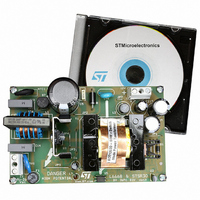
EVALSTSR30-60W
Description
BOARD EVAL USING L6668 & STSR30
Manufacturer
STMicroelectronics
Type
AC/DC Switching Convertersr
Specifications of EVALSTSR30-60W
Mfg Application Notes
EVALSTSR30-60W AppNote
Main Purpose
AC/DC, Primary and Secondary Side
Outputs And Type
1, Isolated
Power - Output
60W
Voltage - Output
12V
Current - Output
5A
Voltage - Input
88 ~ 264VAC
Regulator Topology
Flyback
Frequency - Switching
68kHz
Board Type
Fully Populated
Utilized Ic / Part
L6668, STSR30
Input Voltage
88 V to 264 V
Output Voltage
12 V
Dimensions
120 mm x 75 mm
Product
Power Management Modules
Silicon Manufacturer
ST Micro
Silicon Core Number
L6668 And STSR30
Kit Application Type
Power Management - Voltage Regulator
Application Sub Type
SMPS
Kit Contents
Board
Lead Free Status / RoHS Status
Lead free / RoHS Compliant
For Use With/related Products
L6668, STSR30
Other names
497-6389
EVALSTSR30-60W
EVALSTSR30-60W
Available stocks
Company
Part Number
Manufacturer
Quantity
Price


Adapter features
7/27
The self supply circuit (Q2, R33, C23, L3, D6 and C6) ensures:
●
●
●
A separate rectifying circuit (D11, R19, R28 and C13) derives a voltage level that best
matches the output voltage for accurate overvoltage protection.
As seen, the primary side is quite standard. The most interesting part of this demo board
lies in the secondary side. Here we can find the STSR30, a smart driver for flyback
synchronous rectification (SR). The flyback output diode is substituted with a power
MOSFET (a 75V - 10mΩ) that dramatically reduces the conduction losses. A small Schottky
diode (D1) is mounted in parallel to the MOSFET body diode to keep low the voltage drop
during dead times (while the SR MOS is off and current is circulating in the secondary).
The STSR30 can work in both Continuous and Discontinuous conduction mode and uses 2
pins to synchronize the SR MOSFET with the flyback. The SR MOSFET drain provides the
synchronization information; when the primary side MOSFET is turned off, the drain voltage
of the SR MOSFET falls from V
down to zero. This falling edge is sensed by the CK pin and the IC turns on the SR
MOSFET. Behavior varies according to the flyback transformer operating mode:
●
●
During CCM operation, a certain amount of anticipation is used to prevent cross-conduction
of Q3 and Q1. This anticipation can be selected among three values by biasing the SETANT
pin. In the demo board, the SETANT voltage is 2.5V so the anticipation is 225ns.
The STSR30 works at 5V so it is necessary to obtain such voltage from the output. A low
cost linear regulator (L78L05) is used. For the same reason the gate drive of the IC has a
high value of 5V so a low threshold (logic level) MOSFET has to be used.
Another interesting feature of the STSR30 is its disable input. This is useful at low loads to
turn off the IC and reduce its power consumption. In this condition, the Schottky diode D1
works like in a standard flyback. The information on the load level is obtained by averaging
the voltage on the CK pin using R6, R15 and C4. The CK pin is low (~ 0V) only when the
current in the secondary winding is flowing (SR MOSFET on). Otherwise, the pin is pulled
up at 5V. As the load decreases, the average voltage on CK pin becomes higher and higher.
This voltage level is monitored by the last IC used, the TSM1015, a CV/CC controller that
includes a voltage reference and two op-amps. The reference and the CV op-amp are used
for the voltage control loop of the converter. The CC op-amp is not used for the current
control loop but it acts as a comparator to sense the average voltage of the CK pin. At light
loads, the CK voltage exceeds the threshold (V
STSR30. By adding a little hysteresis (using R40), the DISABLE pin of the STSR30 is driven
digitally with a good noise rejection.
The next two pictures show some waveforms during normal operation at full load. It is
possible to see that the converter operates in CCM at 115 V
a constant V
enough energy during no-load periods
a poor (under UVLO) supply voltage during short-circuit failures
Continuous conduction mode (CCM): the STSR30 uses an internal digital counter to
predict when it has to turn off the SR MOSFET.
Discontinuous conduction mode (DCM): the STSR30 senses the voltage on the
INHIBIT pin (that is, Rdson x Isec) and turns off the SR MOSFET when it reaches the
-25mV threshold (i.e. the current is approaching zero).
CC
voltage with respect to load variations
OUT
+ V
IN
/n (where n is the transformer turns ratio n1/n2)
REF
) and the TSM1015 turns off the
RMS
and in DCM at 230 V
AN2432
RMS
.
Related parts for EVALSTSR30-60W
Image
Part Number
Description
Manufacturer
Datasheet
Request
R

Part Number:
Description:
STMicroelectronics [RIPPLE-CARRY BINARY COUNTER/DIVIDERS]
Manufacturer:
STMicroelectronics
Datasheet:
Part Number:
Description:
STMicroelectronics [LIQUID-CRYSTAL DISPLAY DRIVERS]
Manufacturer:
STMicroelectronics
Datasheet:

Part Number:
Description:
BOARD EVAL FOR MEMS SENSORS
Manufacturer:
STMicroelectronics
Datasheet:
Part Number:
Description:
NPN TRANSISTOR POWER MODULE
Manufacturer:
STMicroelectronics
Datasheet:
Part Number:
Description:
TURBOSWITCH ULTRA-FAST HIGH VOLTAGE DIODE
Manufacturer:
STMicroelectronics
Datasheet:
Part Number:
Description:
Manufacturer:
STMicroelectronics
Datasheet:
Part Number:
Description:
DIODE / SCR MODULE
Manufacturer:
STMicroelectronics
Datasheet:
Part Number:
Description:
DIODE / SCR MODULE
Manufacturer:
STMicroelectronics
Datasheet:
Part Number:
Description:
Search -----> STE16N100
Manufacturer:
STMicroelectronics
Datasheet:
Part Number:
Description:
Search ---> STE53NA50
Manufacturer:
STMicroelectronics
Datasheet:
Part Number:
Description:
NPN Transistor Power Module
Manufacturer:
STMicroelectronics
Datasheet:
Part Number:
Description:
DIODE / SCR MODULE
Manufacturer:
STMicroelectronics
Datasheet: