EVALSTSR30-60W STMicroelectronics, EVALSTSR30-60W Datasheet - Page 17
EVALSTSR30-60W
Manufacturer Part Number
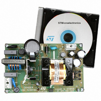
EVALSTSR30-60W
Description
BOARD EVAL USING L6668 & STSR30
Manufacturer
STMicroelectronics
Type
AC/DC Switching Convertersr
Specifications of EVALSTSR30-60W
Mfg Application Notes
EVALSTSR30-60W AppNote
Main Purpose
AC/DC, Primary and Secondary Side
Outputs And Type
1, Isolated
Power - Output
60W
Voltage - Output
12V
Current - Output
5A
Voltage - Input
88 ~ 264VAC
Regulator Topology
Flyback
Frequency - Switching
68kHz
Board Type
Fully Populated
Utilized Ic / Part
L6668, STSR30
Input Voltage
88 V to 264 V
Output Voltage
12 V
Dimensions
120 mm x 75 mm
Product
Power Management Modules
Silicon Manufacturer
ST Micro
Silicon Core Number
L6668 And STSR30
Kit Application Type
Power Management - Voltage Regulator
Application Sub Type
SMPS
Kit Contents
Board
Lead Free Status / RoHS Status
Lead free / RoHS Compliant
For Use With/related Products
L6668, STSR30
Other names
497-6389
EVALSTSR30-60W
EVALSTSR30-60W
Available stocks
Company
Part Number
Manufacturer
Quantity
Price


Figure 41. Hiccup-mode OCP: timing diagram
A second comparator senses the voltage on the current sense input and shuts the IC down if the voltage
at the pin exceeds 1.5 V. Such an anomalous condition is typically generated by either a short circuit of
the secondary rectifier or a shorted secondary winding or a saturated flyback transformer.
This condition is latched as long as the IC is supplied. When the IC is disabled, however, no energy is
coming from the self-supply circuit, then the voltage on the Vcc capacitor will decay and cross the UVLO
threshold after some time, which clears the latch. The internal start-up generator is still off, then the Vcc
voltage still needs to go below its restart voltage before the Vcc capacitor is charged again and the IC re-
started.
Ultimately, either of the above mentioned failures will result in a low-frequency intermittent operation (Hic-
cup-mode operation), with very low stress on the power circuit. The timing diagram of figure 41 illustrates
this operation.
4.6 Power Management
The L6668 is specifically designed to minimize converter's losses under light or no-load conditions, and a
special function has been provided to help the designer meet energy saving requirements even in power-
factor-corrected systems where a PFC pre-regulator precedes the DC-DC converter.
Actually EMC regulations require compliance with low-frequency harmonic emission limits at nominal
load, no limit is envisaged when the converter operates with a light load. Then the PFC pre-regulator can
be turned off, thus saving the no-load consumption of this stage (0.5 to 1W).
To do so, the device provides the PFC_STOP (#14) pin: it is an open collector output, normally low, that
becomes open when the voltage V
This signal will be externally used for switching off the PFC controller and the pre-regulator as shown in
figure 42. To prevent intermittent operation of the PFC stage, 0.5V hysteresis is provided: the PFC_STOP
pin is re-asserted low (which will re-enable the PFC pre-regulator) when V
A capacitor (and a limiting resistor in the hundred ohms), shown in dotted lines, may be used if one wants
to delay PFC turn-off
When the L6668 is in UVLO (Vcc<8.7V) the pin is kept high so as to ensure that the PFC pre-regulator
will start up only after the DC-DC converter governed by the L6668 is activated.
OCP latch
OCP latch
Vcc_OK
Vcc_OK
Vcc OFF
Vcc OFF
Vcc ON
Vcc ON
OUT
OUT
Vcc
Vcc
V CS
V CS
re
re
1.5 V
1.5 V
Secondary diode is shorted here
Secondary diode is shorted here
COMP
falls below 2.2V.
COMP
exceeds 2.7 V.
t
t
t
t
t
t
t
t
t
t
L6668
17/23
Related parts for EVALSTSR30-60W
Image
Part Number
Description
Manufacturer
Datasheet
Request
R

Part Number:
Description:
STMicroelectronics [RIPPLE-CARRY BINARY COUNTER/DIVIDERS]
Manufacturer:
STMicroelectronics
Datasheet:
Part Number:
Description:
STMicroelectronics [LIQUID-CRYSTAL DISPLAY DRIVERS]
Manufacturer:
STMicroelectronics
Datasheet:

Part Number:
Description:
BOARD EVAL FOR MEMS SENSORS
Manufacturer:
STMicroelectronics
Datasheet:
Part Number:
Description:
NPN TRANSISTOR POWER MODULE
Manufacturer:
STMicroelectronics
Datasheet:
Part Number:
Description:
TURBOSWITCH ULTRA-FAST HIGH VOLTAGE DIODE
Manufacturer:
STMicroelectronics
Datasheet:
Part Number:
Description:
Manufacturer:
STMicroelectronics
Datasheet:
Part Number:
Description:
DIODE / SCR MODULE
Manufacturer:
STMicroelectronics
Datasheet:
Part Number:
Description:
DIODE / SCR MODULE
Manufacturer:
STMicroelectronics
Datasheet:
Part Number:
Description:
Search -----> STE16N100
Manufacturer:
STMicroelectronics
Datasheet:
Part Number:
Description:
Search ---> STE53NA50
Manufacturer:
STMicroelectronics
Datasheet:
Part Number:
Description:
NPN Transistor Power Module
Manufacturer:
STMicroelectronics
Datasheet:
Part Number:
Description:
DIODE / SCR MODULE
Manufacturer:
STMicroelectronics
Datasheet: