STEVAL-CBL005V1 STMicroelectronics, STEVAL-CBL005V1 Datasheet - Page 6
STEVAL-CBL005V1
Manufacturer Part Number
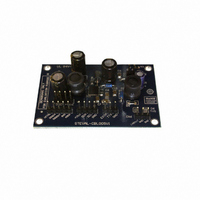
STEVAL-CBL005V1
Description
DEMO BOARD BASED ON LNBH23
Manufacturer
STMicroelectronics
Type
DC/DC Switching Converters, Regulators & Controllersr
Specifications of STEVAL-CBL005V1
Main Purpose
Special Purpose DC/DC, LNB
Outputs And Type
1, Non-Isolated
Voltage - Input
8 ~ 15V
Regulator Topology
Boost
Board Type
Fully Populated
Utilized Ic / Part
LNBH23
Input Voltage
8 V to 15 V
Interface Type
I2C
Product
Power Management Modules
Silicon Manufacturer
ST Micro
Silicon Core Number
LNBH23
Kit Application Type
Power Management
Application Sub Type
LNB Power Supply
Kit Contents
Board
Lead Free Status / RoHS Status
Lead free / RoHS Compliant
Current - Output
-
Voltage - Output
-
Power - Output
-
Frequency - Switching
-
Lead Free Status / Rohs Status
Lead free / RoHS Compliant
For Use With/related Products
LNBH23
Other names
497-8717


Application information
2.4
Figure 2.
2.5
2.6
6/32
Data encoding by external tone generator (EXTM)
In order to improve design flexibility an external tone input pin is available (EXTM). The
EXTM is a logic input pin which activates the 22 kHz tone output, on the V
the LNBH23 integrated tone generator (similarly to the DSQIN pin function). As a matter of
fact, the output tone waveform characteristics will be always internally controlled by the
LNBH23 tone generator and the EXTM signal will be used just as a timing control of the
DiSEqC tone data encoding on the V
for the proper control of the EXTM pin function. Before to send the TTL signal on the EXTM
pin, the V
or TTX bit set HIGH). As soon as the EXTM internal circuit detects the 22 kHz TTL signal
code, it activates the 22 kHz tone on the V
TTL signal presence on the EXTM pin, and it stops with 2 cycles ±25 µs delay after the TTL
signal is expired. Refer to the below
EXTM waveform
I²C interface
The main functions of the IC are controlled via I²C bus by writing 8 bits on the system
register (SR 8 bits in write mode). On the same register there are 8 bits that can be read
back (SR 8 bits in read mode) to provide 8 diagnostic functions: five bits will report the
diagnostic status of five internal monitoring functions (IMON, VMON, TMON, OTF, OLF)
while, three will report the last output voltage register status (EN, VSEL, LLC) received by
the IC (see below diagnostic functions section).
Output voltage selection
When the IC sections are in stand-by mode (EN bit LOW), the power blocks are disabled.
When the regulator blocks are active (EN bit HIGH), the output can be logic controlled to be
13 or 18 V by means of the V
LNBs. Additionally, the LNBH23 is provided with the LLC I²C bit that increases the selected
voltage value by +1 V to compensate the excess of voltage drop along the coaxial cable.
The LNBH23 is also compliant to the USA LNB power supply standards. In order to allow
fast transition of the output voltage from 18 V to 13 V and vice versa, the LNBH23 is
provided with the VCTRL TTL pin which keeps the output to 13 V when it is set LOW and to
18 V when it is set HIGH or floating. V
to use the VCTRL pin to switch the output voltage level. If VCTRL=1 or floating V
(or 19.5 V if LLC=1). With VCTRL=0 V
VCTRL pin controls only the linear regulator V
controlled only through the VSEL and LLC I²C bits, that is: Even if VCTRL=0 (keeping
oTX
tone generator must be previously enabled through the TTX function (TTX pin
SEL
Doc ID 13356 Rev 7
bit (Voltage SELect) for remote controlling of non-DiSEqC
Figure 2
oTX
SEL
oRX
output. A TTL compatible 22 kHz signal is required
and, if required, LLC bits must be set HIGH before
=13.4 V (LLC= either 0 or 1). Be aware that the
oTX
oRX
output with 1.5 cycles ±25 µs delay from the
stage while the step-up V
oTX
UP
pin, by using
voltage is
oRX
LNBH23
=18.5 V
Related parts for STEVAL-CBL005V1
Image
Part Number
Description
Manufacturer
Datasheet
Request
R

Part Number:
Description:
BOARD EVAL FOR MEMS SENSORS
Manufacturer:
STMicroelectronics
Datasheet:

Part Number:
Description:
KIT DEV STARTER ST10F276Z5
Manufacturer:
STMicroelectronics
Datasheet:

Part Number:
Description:
BOARD EVAL UPS 450W VOUT=220V
Manufacturer:
STMicroelectronics
Datasheet:

Part Number:
Description:
BOARD STLM75/STDS75/ST72F651
Manufacturer:
STMicroelectronics
Datasheet:

Part Number:
Description:
EVAL BOARD ENERGY METER MONO
Manufacturer:
STMicroelectronics
Datasheet:

Part Number:
Description:
EVAL BOARD ENERGY METER MONO
Manufacturer:
STMicroelectronics
Datasheet:

Part Number:
Description:
EVAL BOARD ENERGY METER MONO
Manufacturer:
STMicroelectronics
Datasheet:

Part Number:
Description:
BOARD EVAL BASED ON TS2012IQT
Manufacturer:
STMicroelectronics
Datasheet:

Part Number:
Description:
BOARD EVAL FOR TS4962MEIJT
Manufacturer:
STMicroelectronics
Datasheet:

Part Number:
Description:
BOARD DEMO ACCELEROMETER DIL24
Manufacturer:
STMicroelectronics
Datasheet:

Part Number:
Description:
STMicroelectronics [RIPPLE-CARRY BINARY COUNTER/DIVIDERS]
Manufacturer:
STMicroelectronics
Datasheet:
Part Number:
Description:
STMicroelectronics [LIQUID-CRYSTAL DISPLAY DRIVERS]
Manufacturer:
STMicroelectronics
Datasheet:
Part Number:
Description:
BOARD EVAL FOR MEMS SENSORS
Manufacturer:
STMicroelectronics
Datasheet: