EVLVIP27L-12WS STMicroelectronics, EVLVIP27L-12WS Datasheet - Page 19
EVLVIP27L-12WS
Manufacturer Part Number
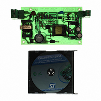
EVLVIP27L-12WS
Description
EVAL BOARD FOR VIPER27LX
Manufacturer
STMicroelectronics
Series
VIPer™ plusr
Specifications of EVLVIP27L-12WS
Main Purpose
AC/DC, Primary Side
Board Type
Fully Populated
Utilized Ic / Part
VIPer27
Lead Free Status / RoHS Status
Lead free / RoHS Compliant
Current - Output
-
Voltage - Output
-
Voltage - Input
-
Power - Output
-
Frequency - Switching
-
Outputs And Type
-
Regulator Topology
-
Lead Free Status / Rohs Status
Lead free / RoHS Compliant
Other names
497-9084


VIPER27
Where:
●
●
●
●
●
●
●
Than, fixed R
Equation 4
The resistor values will be such that the current sourced and sunk by the CONT pin be
within the rated capability of the internal clamp.
Figure 26. OVP timing diagram
COUNTER
COUNTER
COUNTER
COUNTER
STATUS
STATUS
STROBE
STROBE
RESET
RESET
V CONT
V AUX
FAULT
FAULT
V
V
V
OVP
OVP
OVP
DS
DS
V
V
N
N
V
V
R
OVP
OUT OVP
DSEC
DAUX
AUX
SEC
OVP
0
0
0
0
is the OVP threshold (see
N
N
is the auxiliary winding turns
is the secondary winding turns
together R
O
O
is the auxiliary diode forward voltage
is the secondary diode forward voltage
R
R
M
M
LIM,
A
A
2 µs
2 µs
L
L
is the converter output voltage value to activate the OVP set by designer
O
O
0
0
P
P
E
E
according to the desired I
R
R
A
A
T
T
O I
O I
N
N
LIM
0.5 µs
0.5 µs
0
0
make the output voltage divider
0 →1
0 →1
Doc ID 15133 Rev 5
T
T
E
E
M
M
P
P
O
O
R
R
R
A
A
OVP
R
R
Y
Y
Table 8 on page 7
1 →2
1 →2
D
D
S I
S I
T
T
U
U
=
R
R
B
B
R
A
A
Dlim
N
N
LIM
C
C
2 →0
2 →0
E
E
, the R
×
1 k
---------------------- -
–
k
OVP
0
0
OVP
OVP
)
can be calculating by:
0 →1
0 →1
F
F
E
E
E
E
D
D
B
B
A
A
1 → 2
1 → 2
C
C
Operation descriptions
K
K
L
L
O
O
O
O
P
P
F
F
A
A
L I
L I
2 →3
2 →3
U
U
R
R
E
E
3 → 4
3 → 4
19/31
t
t
t
t
t
t
t
t
t
t
t
t
t
t
t
Related parts for EVLVIP27L-12WS
Image
Part Number
Description
Manufacturer
Datasheet
Request
R

Part Number:
Description:
EVAL BOARD FOR VIPER27
Manufacturer:
STMicroelectronics
Datasheet:

Part Number:
Description:
STMicroelectronics [RIPPLE-CARRY BINARY COUNTER/DIVIDERS]
Manufacturer:
STMicroelectronics
Datasheet:
Part Number:
Description:
STMicroelectronics [LIQUID-CRYSTAL DISPLAY DRIVERS]
Manufacturer:
STMicroelectronics
Datasheet:

Part Number:
Description:
BOARD EVAL FOR MEMS SENSORS
Manufacturer:
STMicroelectronics
Datasheet:
Part Number:
Description:
NPN TRANSISTOR POWER MODULE
Manufacturer:
STMicroelectronics
Datasheet:
Part Number:
Description:
TURBOSWITCH ULTRA-FAST HIGH VOLTAGE DIODE
Manufacturer:
STMicroelectronics
Datasheet:
Part Number:
Description:
Manufacturer:
STMicroelectronics
Datasheet:
Part Number:
Description:
DIODE / SCR MODULE
Manufacturer:
STMicroelectronics
Datasheet:
Part Number:
Description:
DIODE / SCR MODULE
Manufacturer:
STMicroelectronics
Datasheet:
Part Number:
Description:
Search -----> STE16N100
Manufacturer:
STMicroelectronics
Datasheet:
Part Number:
Description:
Search ---> STE53NA50
Manufacturer:
STMicroelectronics
Datasheet:
Part Number:
Description:
NPN Transistor Power Module
Manufacturer:
STMicroelectronics
Datasheet: