LM20133EVAL National Semiconductor, LM20133EVAL Datasheet - Page 16
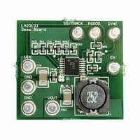
LM20133EVAL
Manufacturer Part Number
LM20133EVAL
Description
BOARD EVAL 3A POWERWISE LM20133
Manufacturer
National Semiconductor
Series
PowerWise®r
Specifications of LM20133EVAL
Main Purpose
DC/DC, Step Down
Outputs And Type
1, Non-Isolated
Voltage - Output
1.2V
Current - Output
3A
Voltage - Input
2.95 ~ 5.5V
Regulator Topology
Buck
Board Type
Fully Populated
Utilized Ic / Part
LM20133
Lead Free Status / RoHS Status
Not applicable / Not applicable
Power - Output
-
Frequency - Switching
-


www.national.com
The value for resistor R
the current through the divider. Typically this resistor will be
selected to be between 10 kΩ and 1 MΩ. Once the value for
R
below to set the desired turn-on voltage.
When designing for a specific turn-on threshold (V
erance on the input supply, enable threshold (V
external resistors needs to be considered to insure proper
turn-on of the device.
The LM20133 features an open drain power good (PGOOD)
pin to sequence external supplies or loads and to provide fault
detection. This pin requires an external resistor (R
PGOOD high while when the output is within the PGOOD tol-
erance window. Typical values for this resistor range from 10
kΩ to 100 kΩ.
TRACKING AN EXTERNAL SUPPLY
By using a properly chosen resistor divider network connect-
ed to the SS/TRK pin, as shown in Figure 7, the output of the
LM20133 can be configured to track an external voltage
source to obtain a simultaneous or ratiometric start up.
Since the Soft-Start charging current I
the SS/TRK pin, the size of R2 should be less than 10 kΩ to
minimize the errors in the tracking output. Once a value for
R2 is selected the value for R1 can be calculated using ap-
propriate equation in Figure 8, to give the desired start up.
Figure 8 shows two common start up sequences; the top
waveform shows a simultaneous start up while the waveform
at the bottom illustrates a ratiometric start up.
FIGURE 6. Sequencing LM20133 with Precision Enable
B
is chosen the resistor R
FIGURE 7. Tracking an External Supply
B
can be selected by the user to control
A
can be solved using the equation
SS
is always present on
30030326
30030320
IH_EN
TO
PG
) the tol-
) to pull
), and
16
A simultaneous start up is preferred when powering most FP-
GAs, DSPs, or other microprocessors. In these systems the
higher voltage, V
voltage, V
vides a more robust power up for these applications since it
avoids turning on any parasitic conduction paths that may ex-
ist between the core and the I/O pins of the processor.
The second most common power on behavior is known as a
ratiometric start up. This start up is preferred in applications
where both supplies need to be at the final value at the same
time.
Similar to the Soft-Start function, the fastest start up possible
is 1 ms regardless of the rise time of the tracking voltage.
When using the track feature the final voltage seen by the SS/
TRACK pin should exceed 1V to provide sufficient overdrive
and transient immunity.
THERMAL CONSIDERATIONS
The thermal characteristics of the LM20133 are specified us-
ing the parameter θ
to the ambient temperature. Although the value of θ
pendant on many variables, it still can be used to approximate
the operating junction temperature of the device.
To obtain an estimate of the device junction temperature, one
may use the following relationship:
and
Where:
T
P
θ
LM20133.
JA
J
IN
is the junction temperature in °C.
is the input power in Watts (P
is the junction to ambient thermal resistance for the
P
FIGURE 8. Common Start Up Sequences
D
OUT2
= P
, powers the core. A simultaneous start up pro-
IN
x (1 - Efficiency) - 1.1 x I
OUT1
JA
, which relates the junction temperature
, usually powers the I/O, and the lower
T
J
= P
D
θ
JA
IN
+ T
= V
A
IN
OUT
x I
IN
2 x DCR
).
JA
is de-
30030321
Related parts for LM20133EVAL
Image
Part Number
Description
Manufacturer
Datasheet
Request
R

Part Number:
Description:
MODULE TXRX BLUETOOTH 2 18SMD
Manufacturer:
Flexipanel
Datasheet:

Part Number:
Description:
MODULE TXRX BLUETOOTH 2 18DIP
Manufacturer:
Flexipanel
Datasheet:

Part Number:
Description:
LM20 2.4V, 10?A, SC70, micro SMD Temperature Sensor
Manufacturer:
National Semiconductor
Datasheet:
Part Number:
Description:
National Semiconductor [8-Bit D/A Converter]
Manufacturer:
National Semiconductor
Datasheet:
Part Number:
Description:
National Semiconductor [Media Coprocessor]
Manufacturer:
National Semiconductor
Datasheet:
Part Number:
Description:
Digitally Controlled Tone and Volume Circuit with Stereo Audio Power Amplifier, Microphone Preamp Stage and National 3D Sound
Manufacturer:
National Semiconductor
Datasheet:
Part Number:
Description:
Digitally Controlled Tone and Volume Circuit with Stereo Audio Power Amplifier, Microphone Preamp Stage and National 3D Sound
Manufacturer:
National Semiconductor
Datasheet:
Part Number:
Description:
AC97 Rev 2 Codec with Sample Rate Conversion and National 3D Sound
Manufacturer:
National Semiconductor
Part Number:
Description:
Manufacturer:
National Semiconductor
Datasheet:
Part Number:
Description:
Manufacturer:
National Semiconductor
Datasheet:
Part Number:
Description:
General Purpose, Low Voltage, Low Power, Rail-to-Rail Output Operational Amplifiers
Manufacturer:
National Semiconductor
Datasheet:
Part Number:
Description:
8-bit 20 MSPS flash A/D converter.
Manufacturer:
National Semiconductor
Datasheet:
Part Number:
Description:
Low Noise Quad Operational Amplifier
Manufacturer:
National Semiconductor
Datasheet:
Part Number:
Description:
Quad Differential Line Receivers
Manufacturer:
National Semiconductor
Datasheet: