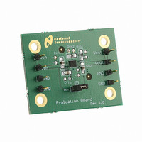
LM2750LD-ADJEV National Semiconductor, LM2750LD-ADJEV Datasheet - Page 10

LM2750LD-ADJEV
Manufacturer Part Number
LM2750LD-ADJEV
Description
BOARD EVAL LM2750LD-ADJ
Manufacturer
National Semiconductor
Series
PowerWise®r
Specifications of LM2750LD-ADJEV
Main Purpose
DC/DC, Step Up
Outputs And Type
1, Non-Isolated
Voltage - Output
3.8 ~ 5.2V
Current - Output
120mA
Voltage - Input
2.7 ~ 5.6V
Regulator Topology
Boost
Frequency - Switching
1.7MHz
Board Type
Fully Populated
Utilized Ic / Part
LM2750
Lead Free Status / RoHS Status
Not applicable / Not applicable
Power - Output
-
Lead Free Status / Rohs Status
Not Compliant
www.national.com
Operation Description
Application Information
OUTPUT VOLTAGE RIPPLE
The amount of voltage ripple on the output of the LM2750 is
highly dependent on the application conditions: output cur-
rent and the output capacitor, specifically. A simple approxi-
mation of output ripple is determined by calculating the
amount of voltage droop that occurs when the output of the
LM2750 is not being driven. This occurs during the charge
phase (φ1). During this time, the load is driven solely by the
charge on the output capacitor. The magnitude of the ripple
thus follows the basic discharge equation for a capacitor (I =
C x dV/dt), where discharge time is one-half the switching
period, or 0.5/F
A more thorough and accurate examination of factors that
affect ripple requires including effects of phase non-overlap
times and output capacitor equivalent series resistance
(ESR). In order for the LM2750 to operate properly, the two
phases of operation must never coincide. (If this were to
happen all switches would be closed simultaneously, short-
ing input, output, and ground). Thus, non-overlap time is built
into the clocks that control the phases. Since the output is
not being driven during the non-overlap time, this time
should be accounted for in calculating ripple. Actual output
capacitor discharge time is approximately 60% of a switch-
ing period, or 0.6/F
The ESR of the output capacitor also contributes to the
output voltage ripple, as there is effectively an AC voltage
drop across the ESR due to current switching in and out of
the capacitor. The following equation is a more complete
calculation of output ripple than presented previously, taking
into account phase non-overlap time and capacitor ESR.
SW
. Put simply,
SW
.
FIGURE 2. LM2750-ADJ Typical Application Circuit
(Continued)
10
A low-ESR ceramic capacitor is recommended on the output
to keep output voltage ripple low. Placing multiple capacitors
in parallel can reduce ripple significantly, both by increasing
capacitance and reducing ESR. When capacitors are in
parallel, ESR is in parallel as well. The effective net ESR is
determined according to the properties of parallel resistance.
Two identical capacitors in parallel have twice the capaci-
tance and half the ESR as compared to a single capacitor of
the same make. On a similar note, if a large-value, high-ESR
capacitor (tantalum, for example) is to be used as the pri-
mary output capacitor, the net output ESR can be signifi-
cantly reduced by placing a low-ESR ceramic capacitor in
parallel with this primary output capacitor.
CAPACITORS
The LM2750 requires 3 external capacitors for proper opera-
tion. Surface-mount multi-layer ceramic capacitors are rec-
ommended. These capacitors are small, inexpensive and
have very low equivalent series resistance (≤10mΩ typ.).
Tantalum capacitors, OS-CON capacitors, and aluminum
electrolytic capacitors generally are not recommended for
use with the LM2750 due to their high ESR, as compared to
ceramic capacitors.
For most applications, ceramic capacitors with X7R or X5R
temperature characteristic are preferred for use with the
LM2750. These capacitors have tight capacitance tolerance
(as good as
±
and typically have little voltage coefficient. Capacitors with
Y5V and/or Z5U temperature characteristic are generally not
recommended. These types of capacitors typically have
wide capacitance tolerance (+80%, -20%), vary significantly
over temperature (Y5V: +22%, -82% over -30
range; Z5U: +22%, -56% over +10
have poor voltage coefficients. Under some conditions, a
nominal 1µF Y5V or Z5U capacitor could have a capacitance
of only 0.1µF. Such detrimental deviation is likely to cause
these Y5V and Z5U of capacitors to fail to meet the minimum
capacitance requirements of the LM2750.
The table below lists some leading ceramic capacitor manu-
facturers.
15% over -55
±
10%), hold their value over temperature (X7R:
o
C to 125
o
C; X5R:
±
15% over -55
o
C to +85
20035123
o
C range), and
o
o
C to +85
C to 85
o
C),
o
C


