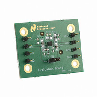
LM2750LD-ADJEV National Semiconductor, LM2750LD-ADJEV Datasheet - Page 13

LM2750LD-ADJEV
Manufacturer Part Number
LM2750LD-ADJEV
Description
BOARD EVAL LM2750LD-ADJ
Manufacturer
National Semiconductor
Series
PowerWise®r
Specifications of LM2750LD-ADJEV
Main Purpose
DC/DC, Step Up
Outputs And Type
1, Non-Isolated
Voltage - Output
3.8 ~ 5.2V
Current - Output
120mA
Voltage - Input
2.7 ~ 5.6V
Regulator Topology
Boost
Frequency - Switching
1.7MHz
Board Type
Fully Populated
Utilized Ic / Part
LM2750
Lead Free Status / RoHS Status
Not applicable / Not applicable
Power - Output
-
Lead Free Status / Rohs Status
Not Compliant
LM2750 LED Drive Application
The LM2750 is an excellent part for driving white and blue
LEDs for display backlighting and other general-purpose
lighting functions. The circuits of Figure 5 and Figure 6 show
LED driver circuits for the LM2750-5.0 and the LM2750-ADJ,
respectively. Simply placing a resistor (R) in series with each
LED sets the current through the LEDs:
In the equation above, I
a particular LED, and V
at the given current. As can be seen in the equation above,
LED current will vary with changes in LED forward voltage
(V
mismatch from one LED to the next.
The feedback pin of the LM2750-ADJ can be utilized to help
better control brightness levels and negate the effects of
LED forward voltage variation. As shown in Figure 6, con-
necting the feedback pin to the primary LED-resistor junction
(LED1-R1) regulates the current through that LED. The volt-
age across the primary resistor (R1) is the feedback pin
I
LED
LED
). Mismatch of LED currents will result in brightness
= (V
OUT
- V
LED
) / R
LED
LED
is the forward voltage of the LED
is the current that flows through
FIGURE 6. LM2750-ADJ LED Drive Application Circuit
FIGURE 5. LM2750-5.0 LED Drive Application Circuit
13
voltage (1.23V typ.), and the current through the LED is the
current through that resistor. Current through all other LEDs
(LEDx) will not be regulated, however, and will vary with LED
forward voltage variations. When using the LM2750-ADJ in
current-mode, LED currents can be calculated with the
equations below:
The current-mode configuration does not improve brightness
matching from one LED to another in a single circuit, but will
keep currents similar from one circuit to the next. For ex-
ample: if there is forward voltage mismatch from LED1 to
LED2 on a single board, the current-mode LM2750-ADJ
solution provides no benefit. But if the forward voltage of
LED1 on one board is different than the forward voltage of
LED1 on another board, the currents through LED1 in both
phones will match. THis helps keep LED currents fairly
consistent from one product to the next, adn helps to offset
lot-to-lot variation of LED forward voltage characteristics.
I
I
LED1
LEDx
= (1.23V + V
= 1.23V / R1
LED1
- V
LEDx
) / Rx
20035124
20035125
www.national.com


