NCP1052GEVB ON Semiconductor, NCP1052GEVB Datasheet - Page 2
NCP1052GEVB
Manufacturer Part Number
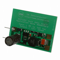
NCP1052GEVB
Description
EVAL BOARD FOR NCP1052G
Manufacturer
ON Semiconductor
Specifications of NCP1052GEVB
Design Resources
NCP1052 Eval Board BOM NCP1052GEVB Gerber Files NCP1052 Demo Board Schematic
Main Purpose
AC/DC, Non-Isolated
Outputs And Type
1, Non-Isolated
Power - Output
1.2W
Voltage - Output
120V
Current - Output
100mA
Voltage - Input
85 ~ 265VAC
Regulator Topology
Boost, Buck
Frequency - Switching
136kHz
Board Type
Fully Populated
Utilized Ic / Part
NCP1052
Lead Free Status / RoHS Status
Lead free / RoHS Compliant
For Use With/related Products
NCP1052G
Other names
NCP1052GEVBOS


through the output and a low-frequency ripple will be found
in the output voltage. Hence, the value of C
small enough to increase this charging frequency f
order to reduce output voltage ripple because some
efficiency is lost due to this low-frequency ripple.
charging current path is blocked by diode D and hence the
charging of C
However, it still affects the output voltage indirectly and
slightly by adding some low-frequency noise on the
inductor. Hence, small value of C
Input
Input
In Figure 2b it is noted that in the buck-boost topology the
D
Figure 3. Output Voltage Couples to C
3
D
C
3
3
C
I
start
3
I
start
D
Figure 2. Charging Current of C
V
D
FB
CC
2
V
FB
CC
does not affect the output voltage directly.
C
2
D
Charging Current
2
D
C
S
2
(b) Buck-boost
(b) Buck-boost
Z
2
C
S
2
Z
1
2
(a) Buck
(a) Buck
L
C
C
D
1
D
D
C
D
1
R
1
D
1
1
1
D
1
R
1
2
1
L
is also wanted.
R
R
1
1
C
C
2
is needed to be
Z
Z
1
1
2
1
V
V
out
out
with a
Output
Output
VCC
http://onsemi.com
AND8098/D
in
2
to transfer the magnitude of output voltage to a voltage
across C
Figure 3, when the main switch inside the IC is opened and
the diode D is closed. In buck, the potential of the IC
reference ground (pin S) becomes almost 0 V in this
moment. In buck-boost, the potential of the IC reference
ground (pin S) becomes -V
in C
hand, when main switch is closed and the diode D is opened,
diode D
and V
normal operation of the buck and buck-boost converter.
possibly greater than the output voltage especially when
output current or output ripple is too large. It directly affects
the load regulation of the circuit since the IC regulates the
output voltage based on the voltage in C
it, larger values of L and R
charging speed of C
voltage in C
can be pulled up and a good regulation is made.
usually unwanted because it is bulky. Hence, resistor R
recommended. Larger value of R
voltage. Hence, it is called as a “pull-up resistor” and it can
help to pull up the output voltage slightly.
feedback to the feedback (FB) pin of the NCP1052 through
a diode D
high, there will be a greater-than-50 mA current inserting
into the feedback pin of the NCP1052. The NCP1052 will
stop switching when it happens. When output voltage is not
high enough, the current inserting into the feedback is
smaller than 50 mA. The NCP1052 enables switching and
power is delivered to the output until the output voltage is
too high again.
inserting into the feedback pin because the switching of
NCP1052 can also be stopped when there is a
greater-than-50 mA current sinking from the FB pin. The
purpose of the zener diode Z
threshold. The FB pin of NCP1052 with a condition of
50 mA sourcing current is about 4.3 V. The volt-drop of the
diode D
voltage can be loosely set as follows:
According to (1), the possible minimum output voltage of
the circuit is 5.0 V when there is no zener diode Z
duty cycle to the minimum value but the output voltage is
still possible to be very high because there is no passive
component in the circuit try to absorb the energy. As a result,
The function of diode D
It is noted that the instantaneous voltage in C
Larger value of L can help the load regulation but it
The voltage in C
The purpose of the diode D
If there is no load, the IC will automatically minimize its
1
in
will be charged to the output voltage. On the other
+V
2
1
1
is loosely about 0.7 V at 50 mA. Hence, the output
is reverse biased by a voltage with magnitude V
2
so that the IC can regulate the output voltage. In
out
and zener diode Z
1
V out + zener ) 4.3 V ) 0.7 V
respectively. Hence, D
so that output voltage at high output current
+ zener ) 5 V
1
. It reduces the maximum instantaneous
1
representing the output voltage is
1
, capacitor C
out
1
2
2
. When output voltage is too
in this moment. The voltage
2
can help to slow down the
is to set the output voltage
is to ensure the current is
1
makes higher output
1
1
does not affect the
1
and resistor R
. In order to solve
1
2
.
can be
(eq. 1)
1
1
are
in
is
Related parts for NCP1052GEVB
Image
Part Number
Description
Manufacturer
Datasheet
Request
R

Part Number:
Description:
ON Semiconductor [VOLTAGE REGULATOR]
Manufacturer:
ON Semiconductor
Datasheet:
Part Number:
Description:
357-036-542-201 CARDEDGE 36POS DL .156 BLK LOPRO
Manufacturer:
ON Semiconductor
Datasheet:
Part Number:
Description:
357-036-542-201 CARDEDGE 36POS DL .156 BLK LOPRO
Manufacturer:
ON Semiconductor
Datasheet:
Part Number:
Description:
357-036-542-201 CARDEDGE 36POS DL .156 BLK LOPRO
Manufacturer:
ON Semiconductor
Datasheet:
Part Number:
Description:
357-036-542-201 CARDEDGE 36POS DL .156 BLK LOPRO
Manufacturer:
ON Semiconductor
Datasheet:
Part Number:
Description:
357-036-542-201 CARDEDGE 36POS DL .156 BLK LOPRO
Manufacturer:
ON Semiconductor
Datasheet:
Part Number:
Description:
357-036-542-201 CARDEDGE 36POS DL .156 BLK LOPRO
Manufacturer:
ON Semiconductor
Datasheet:
Part Number:
Description:
357-036-542-201 CARDEDGE 36POS DL .156 BLK LOPRO
Manufacturer:
ON Semiconductor
Datasheet:
Part Number:
Description:
357-036-542-201 CARDEDGE 36POS DL .156 BLK LOPRO
Manufacturer:
ON Semiconductor
Datasheet:
Part Number:
Description:
357-036-542-201 CARDEDGE 36POS DL .156 BLK LOPRO
Manufacturer:
ON Semiconductor
Datasheet:
Part Number:
Description:
357-036-542-201 CARDEDGE 36POS DL .156 BLK LOPRO
Manufacturer:
ON Semiconductor
Datasheet:
Part Number:
Description:
Manufacturer:
ON Semiconductor
Datasheet:
Part Number:
Description:
Manufacturer:
ON Semiconductor
Datasheet:
Part Number:
Description:
Manufacturer:
ON Semiconductor
Datasheet: