DC1319B-A Linear Technology, DC1319B-A Datasheet - Page 17
DC1319B-A
Manufacturer Part Number
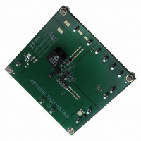
DC1319B-A
Description
BOARD EVAL LED DRIVER LT3756
Manufacturer
Linear Technology
Specifications of DC1319B-A
Current - Output / Channel
500mA
Outputs And Type
1, Non-Isolated
Voltage - Output
100V
Features
Dimmable
Voltage - Input
8 ~ 80V
Utilized Ic / Part
LT3756
Lead Free Status / RoHS Status
Lead free / RoHS Compliant
Other names
DC1319A-A
DC1319A-A
DC1319A-A


Loop Compensation
The LT3756 uses an internal transconductance error ampli-
fier whose VC output compensates the control loop. The
external inductor, output capacitor and the compensation
resistor and capacitor determine the loop stability.
The inductor and output capacitor are chosen based on
performance, size and cost. The compensation resistor
and capacitor at VC are selected to optimize control loop
response and stability. For typical LED applications, a
2.2nF compensation capacitor at VC is adequate, and
a series resistor should always be used to increase the
slew rate on the VC pin to maintain tighter regulation of
LED current during fast transients on the input supply to
the converter.
Board Layout
The high speed operation of the LT3756 demands careful
attention to board layout and component placement. The
exposed pad of the package is the only GND terminal of
the IC and is also important for thermal management of
the IC. It is crucial to achieve a good electrical and thermal
contact between the exposed pad and the ground plane of
the board. To reduce electromagnetic interference (EMI), it
applicaTions inForMaTion
is important to minimize the area of the high dV/dt switching
node between the inductor, switch drain and anode of the
Schottky rectifier. Use a ground plane under the switching
node to eliminate interplane coupling to sensitive signals.
The lengths of the high dI/dt traces: 1) from the switch
node through the switch and sense resistor to GND, and
2) from the switch node through the Schottky rectifier and
filter capacitor to GND should be minimized. The ground
points of these two switching current traces should come
to a common point then connect to the ground plane under
the LT3756. Likewise, the ground terminal of the bypass
capacitor for the INTV
the GND of the switching path. Typically, this requirement
will result in the external switch being closest to the IC,
along with the INTV
the compensation network and other DC control signals
should be star connected to the underside of the IC. Do
not extensively route high impedance signals such as FB
and VC, as they may pick up switching noise. In particular,
avoid routing FB and PWMOUT in parallel for more than a
few millimeters on the board. Likewise, minimize resistance
in series with the SENSE input to avoid changes (most
likely reduction) to the switch current limit threshold.
LT3756/LT3756-1/LT3756-2
CC
CC
bypass capacitor. The ground for
regulator should be placed near
375612fb
Related parts for DC1319B-A
Image
Part Number
Description
Manufacturer
Datasheet
Request
R

Part Number:
Description:
CD ROM LINEARVIEW DATASHEETS
Manufacturer:
Linear Technology

Part Number:
Description:
Standalone Linear Li-Ion Battery Charger with Thermal Regulation in ThinSOT
Manufacturer:
Linear Technology Corporation
Datasheet:
Part Number:
Description:
Low noise, high frequency, 8th order linear phase lowpass filter
Manufacturer:
Linear Technology Corporation
Datasheet:
Part Number:
Description:
Manufacturer:
Linear Technology Corporation
Datasheet:
Part Number:
Description:
Manufacturer:
Linear Technology Corporation
Datasheet:
Part Number:
Description:
Manufacturer:
Linear Technology Corporation
Datasheet:
Part Number:
Description:
Manufacturer:
Linear Technology Corporation
Datasheet:
Part Number:
Description:
Manufacturer:
Linear Technology Corporation
Datasheet:
Part Number:
Description:
Manufacturer:
Linear Technology Corporation
Datasheet:
Part Number:
Description:
Manufacturer:
Linear Technology Corporation
Datasheet:
Part Number:
Description:
Dual and Quad, JFET Input Precision High Speed Op Amps
Manufacturer:
Linear Technology Corporation
Datasheet:
Part Number:
Description:
Manufacturer:
Linear Technology Corporation
Datasheet:
Part Number:
Description:
1, 2, 6 and 8 Channel, 10-Bit Serial I/O Data Acquisition Systems
Manufacturer:
Linear Technology Corporation
Datasheet:
Part Number:
Description:
Manufacturer:
Linear Technology Corporation
Datasheet:
Part Number:
Description:
Universal dual filter building block
Manufacturer:
Linear Technology Corporation
Datasheet: