SSL2101T/DB/FBCB120V,598 NXP Semiconductors, SSL2101T/DB/FBCB120V,598 Datasheet - Page 4
SSL2101T/DB/FBCB120V,598
Manufacturer Part Number
SSL2101T/DB/FBCB120V,598
Description
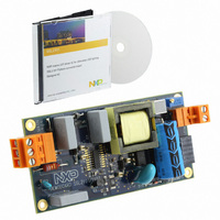
BOARD EVAL LED DRIVER SS2101
Manufacturer
NXP Semiconductors
Type
DC/DC Switching Converters, Regulators & Controllersr
Specifications of SSL2101T/DB/FBCB120V,598
Current - Output / Channel
400 mA ~ 800 mA
Outputs And Type
1, Isolated
Voltage - Output
9 ~ 23 V
Features
Dimmable, TRIAC Dimmable
Voltage - Input
120VAC
Utilized Ic / Part
SSL2101
Input Voltage
120 V
Board Size
103 mm x 50 mm x 20 mm
Maximum Operating Temperature
+ 100 C
Minimum Operating Temperature
- 40 C
Operating Supply Voltage
8.5 V to 40 V
Product
Power Management Modules
Dimensions
103 mm x 50 mm x 20 mm
For Use With/related Products
SSL2101T
Lead Free Status / RoHS Status
Lead free / RoHS Compliant
Lead Free Status / RoHS Status
Lead free / RoHS Compliant, Lead free / RoHS Compliant
Other names
568-4812


NXP Semiconductors
3. Connecting the board
UM10341
User manual
Fig 2.
Board connection diagram
Remark: All components referred to in the text can be located on
schematic diagram”
diagram”.
The board can be optimized for a 230 V 50 Hz or a 120 V 60 Hz mains supply. In addition
to the mains voltage optimization, the board is designed to work with multiple high power
LEDs with a total working voltage of between 9 V and 23 V. The output current can be
limited using trimmer R20. On request, a dedicated LED load can be delivered that is to
be connected to K3. Connector K2 can be used to attach other LED loads. The output
voltage is limited to 25 V. When attaching a LED load to an operational board (hot
plugging) an inrush peak current will occur due to the discharge of capacitor C6. After
frequent discharges, the LEDs may deteriorate or become damaged.
If a galvanic isolated transformer is used, it should be placed between the AC source and
the dimmer/demo board. Connect a user defined LED (string) to connector K2 as shown
in
connector.
Remark: When the board is placed in a metal enclosure, the middle pin of connector K1
can be connected to the metal casing for grounding.
Figure
K1
N
L
2. Note that the anode of the LED (string) is connected to the bottom side of this
All information provided in this document is subject to legal disclaimers.
and connectors can be found on
Rev. 2 — 3 February 2011
SSL2101 12 W mains dimmable LED driver
Figure 2 “Board connection
−
+
K3
019aaa820
K2
−
+
LED−
LED+
Figure 8 “Board
LED−
LED+
UM10341
© NXP B.V. 2011. All rights reserved.
4 of 24
Related parts for SSL2101T/DB/FBCB120V,598
Image
Part Number
Description
Manufacturer
Datasheet
Request
R

Part Number:
Description:
BOARD EVAL LED DRIVER SS2101
Manufacturer:
NXP Semiconductors
Datasheet:

Part Number:
Description:
NXP Semiconductors designed the LPC2420/2460 microcontroller around a 16-bit/32-bitARM7TDMI-S CPU core with real-time debug interfaces that include both JTAG andembedded trace
Manufacturer:
NXP Semiconductors
Datasheet:

Part Number:
Description:
NXP Semiconductors designed the LPC2458 microcontroller around a 16-bit/32-bitARM7TDMI-S CPU core with real-time debug interfaces that include both JTAG andembedded trace
Manufacturer:
NXP Semiconductors
Datasheet:
Part Number:
Description:
NXP Semiconductors designed the LPC2468 microcontroller around a 16-bit/32-bitARM7TDMI-S CPU core with real-time debug interfaces that include both JTAG andembedded trace
Manufacturer:
NXP Semiconductors
Datasheet:
Part Number:
Description:
NXP Semiconductors designed the LPC2470 microcontroller, powered by theARM7TDMI-S core, to be a highly integrated microcontroller for a wide range ofapplications that require advanced communications and high quality graphic displays
Manufacturer:
NXP Semiconductors
Datasheet:
Part Number:
Description:
NXP Semiconductors designed the LPC2478 microcontroller, powered by theARM7TDMI-S core, to be a highly integrated microcontroller for a wide range ofapplications that require advanced communications and high quality graphic displays
Manufacturer:
NXP Semiconductors
Datasheet:
Part Number:
Description:
The Philips Semiconductors XA (eXtended Architecture) family of 16-bit single-chip microcontrollers is powerful enough to easily handle the requirements of high performance embedded applications, yet inexpensive enough to compete in the market for hi
Manufacturer:
NXP Semiconductors
Datasheet:
Part Number:
Description:
The XA-S3 device is a member of Philips Semiconductors? XA(eXtended Architecture) family of high performance 16-bitsingle-chip microcontrollers
Manufacturer:
NXP Semiconductors
Datasheet:

Part Number:
Description:
The NXP BlueStreak LH75401/LH75411 family consists of two low-cost 16/32-bit System-on-Chip (SoC) devices
Manufacturer:
NXP Semiconductors
Datasheet:
Part Number:
Description:
The NXP LPC3130/3131 combine an 180 MHz ARM926EJ-S CPU core, high-speed USB2
Manufacturer:
NXP Semiconductors
Datasheet:
Part Number:
Description:
The NXP LPC3141 combine a 270 MHz ARM926EJ-S CPU core, High-speed USB 2
Manufacturer:
NXP Semiconductors
Part Number:
Description:
The NXP LPC3143 combine a 270 MHz ARM926EJ-S CPU core, High-speed USB 2
Manufacturer:
NXP Semiconductors

Part Number:
Description:
The NXP LPC3152 combines an 180 MHz ARM926EJ-S CPU core, High-speed USB 2
Manufacturer:
NXP Semiconductors
Part Number:
Description:
The NXP LPC3154 combines an 180 MHz ARM926EJ-S CPU core, High-speed USB 2
Manufacturer:
NXP Semiconductors