LM3423MHBKBSTEV/NOPB National Semiconductor, LM3423MHBKBSTEV/NOPB Datasheet
LM3423MHBKBSTEV/NOPB
Specifications of LM3423MHBKBSTEV/NOPB


Related parts for LM3423MHBKBSTEV/NOPB

LM3423MHBKBSTEV/NOPB Summary of contents
Page 1
... DIM input suitable for fast PWM dimming of the output, cycle-by-cycle current limit, LED ready flag, fault flag, programmable fault timer, and thermal shutdown. © 2008 National Semiconductor Corporation National Semiconductor Application Note 1907 Matthew Reynolds ...
Page 2
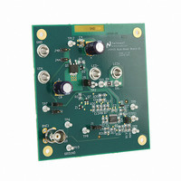
Board Connections and Configuration Connecting the evaluation board to a power supply and load is accomplished through banana-plug type connectors (refer to Table 1). Connector Designation V IN GND LED+ LED- Configuration of the evaluation board is accomplished through the ...
Page 3
Test Point Designation TP9 TP10 TP11 TP12 LM3423 TSSOP Pin Connection Board Features This evaluation board has all the necessary connections and jumpers to evaluate the LM3423 controller in a boost con- verter topology with the following operating features and ...
Page 4
This establishes a current gain determined by a resistor ratio consisting of R17 and R7 along with R9 as described in the equation: Substituting in the resistor values as listed in the board schematic gives a fixed I current of ...
Page 5
The worst case ripple is seen when the input voltage is at its lowest magnitude. This is true if we can say that the output voltage stays relatively constant. Design Example: ≊ V 28V 18V IN-MIN V ...
Page 6
FIGURE 4. MOSFET R Sensing Configuration DS(ON) TABLE 5. MOSFET R Sensing Configuration DS(ON) Jumper J2 J3 J4A, J4B R6 The trade-off will be less accuracy and performance flexibility for reduced component count, and increased efficiency. The current limit (I ...
Page 7
COMPENSATION The LM3423’s error amplifier (EA transconductance type amplifier, which allows for easy single-pin compensation. When a capacitor is used on the output of the converter to reduce LED ripple current, a two pole system results. To offset ...
Page 8
UNDER-VOLTAGE PROTECTION The LM3423 can be configured for under-voltage lockout (UVLO) protection with hysteresis using the dimming input nDIM (pin 8) and a resistor divider from input voltage to ground. UVLO protects the power devices during power sup- ply startup ...
Page 9
Evaluation Board Test Procedure PROPER BOARD CONNECTIONS Be sure to choose the correct wire size when connecting the source supply and load. Monitor the current into and out of the unit under test (UUT). Monitor the voltages directly at the ...
Page 10
Bill of Materials Part Capacitor 0805 1200 pF, 100V C4, C11 Capacitor 1210 10 µF, 25V C5 Capacitor 0805 0.022 µF, 50V C6 Capacitor 0805 0.01 µF, 50V C7, C8 Capacitor 330 µF, 35V 5mm ...
Page 11
LM3421 Buck-Boost Design Example (High Side Current Sense & High Speed Dimming) LM3421 Design Example: High Side Current Sense with High Speed Dimming 11 30080822 www.national.com ...
Page 12
LM3421 Buck-Boost Design Example (High Side Current Sense) www.national.com LM3421 Design Example: High Side Current Sense 12 30080832 ...
Page 13
13 www.national.com ...
Page 14
... For more National Semiconductor product information and proven design tools, visit the following Web sites at: Products Amplifiers www.national.com/amplifiers Audio www.national.com/audio Clock and Timing www.national.com/timing Data Converters www.national.com/adc Interface www.national.com/interface LVDS www.national.com/lvds Power Management www.national.com/power Switching Regulators www.national.com/switchers LDOs www.national.com/ldo LED Lighting www ...