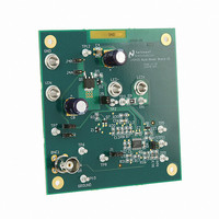
LM3423MHBKBSTEV/NOPB National Semiconductor, LM3423MHBKBSTEV/NOPB Datasheet - Page 7

LM3423MHBKBSTEV/NOPB
Manufacturer Part Number
LM3423MHBKBSTEV/NOPB
Description
BOARD EVAL BUCK BOOST LM3423
Manufacturer
National Semiconductor
Series
PowerWise®r
Specifications of LM3423MHBKBSTEV/NOPB
Current - Output / Channel
1A
Outputs And Type
1, Non-Isolated
Voltage - Output
35V
Features
Dimmable
Voltage - Input
4.5 ~ 35V
Utilized Ic / Part
LM3423
Lead Free Status / RoHS Status
Lead free / RoHS Compliant
Other names
LM3423MHBKBSTEV
COMPENSATION
The LM3423’s error amplifier (EA) is a transconductance type
amplifier, which allows for easy single-pin compensation.
When a capacitor is used on the output of the converter to
reduce LED ripple current, a two pole system results. To offset
one of the two poles, and guarantee loop stability, a zero is
introduced at the output of the EA. This takes the form of a
resistor in series with a compensation capacitor (R21 and
C5). The value of the EA resistor and capacitor is calculated
to give the same RC time constant as the output capacitor
and the dynamic resistance (RD) of the LED string.
LED DYNAMIC RESISTANCE
When the load is an LED or string of LEDs, the load resistance
is replaced with the dynamic resistance (r
sense resistor. LEDs are PN junction diodes, and their dy-
namic resistance shifts as their forward current changes.
Dividing V
times higher than the true r
1 Amp is a typical driving current for 3W LEDs, and the cal-
culation below shows how the dynamic resistance of a 5W
white InGaN was determined at 1A:
ΔV
ΔI
r
Dynamic resistances combine in series and parallel like linear
resistors, hence for a string of 'n' series-connected LEDs the
total dynamic resistance would be:
r
Now that we have calculated the dynamic resistance of our
LED string, we can calculate the compensation resistor and
capacitor values (C5 and R21).
C
r
Choose C5 to equal 100 nF, therefore R21 equals 4.32 kΩ
D
D
D
OUT
-TOTAL = n x r
-TOTAL x C
F
= ΔV
F
= 1.5A - 0A = 1.5A
= 3.85V - 3.48V = 370 mV
= 330 µF and r
F
/ ΔI
F
by I
F
FIGURE 5. Dynamic Resistance
OUT
= 370 mV / 1.5A = 250 mΩ
(r
F
D-TOTAL
D
leads to incorrect results that are 5 to 10
= 1.95Ω x 220 µF = 430E-6
+ R
D
= 1.35Ω
SNS
x C
= 5(250 mV) + 100 mΩ = 1.35Ω
D
OUT
value.
) = (R21 x C5)
D
) and the current
30080831
7
OVERVOLTAGE PROTECTION
An over-voltage protection (OVP) with programmable hys-
teresis feature is available on the LM3423 to protect the
device from damage when the boosted output voltage goes
above a maximum value.
The OVP threshold is set up by the resister divider network of
R22 and R20 which is referenced to the regulated output volt-
age (VO). The OVP threshold and hysteresis can be pro-
grammed completely independent of each other. OVP
hysteresis is accomplished with an internal 23 µA current
source that is switched on and off into the impedance of the
OVP set-point resistor divider. When the OVP pin exceeds
1.24V, the current source is activated to instantly raise the
voltage at the OVP pin. When the OVP pin voltage falls below
the 1.24V threshold, the current source is turned off, causing
the voltage at the OVP pin to fall.
Calculating OVP hysterisis and set points:
Step 1: Determine V
Step 2: Calculate R20
The V
sis) is described by the equation:
The evaluation board is already configured with OVP, and the
V
55V with 13V of hysteresis. OVP will therefore release when
V
O
O
OVP threshold is programmed on the evaluation board to
reaches 42V (R20 = 562 kΩ, R22 = 12.4 kΩ).
O
OVP release point (which includes the OVP hystere-
FIGURE 6. OVP Circuit
HYST
, V
HYST
= (V
OVP_UP
– V
OVP_DN
www.national.com
30080812
)


