NCP5006EVB ON Semiconductor, NCP5006EVB Datasheet - Page 8
NCP5006EVB
Manufacturer Part Number
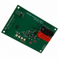
NCP5006EVB
Description
EVAL BOARD FOR NCP5006
Manufacturer
ON Semiconductor
Specifications of NCP5006EVB
Design Resources
NCP5006 Demo Board BOM NCP5006EVB Gerber Files NCP5006 Demo Board Schematic
Current - Output / Channel
15mA
Outputs And Type
1, Non-Isolated
Voltage - Output
22V
Voltage - Input
3.6V
Utilized Ic / Part
NCP5006
Core Chip
NCP5006
Topology
Boost
No. Of Outputs
1
Development Tool Type
Hardware - Eval/Demo Board
Mcu Supported Families
NCP5006
Lead Free Status / RoHS Status
Lead free / RoHS Compliant
Features
-
Lead Free Status / Rohs Status
Lead free / RoHS Compliant
For Use With/related Products
NCP5006
Other names
NCP5006EVBOS


Output Current Range Set−Up
drop across the sense resistor R1. The voltage drop is
constantly monitored internally, and maximum peak
current allowed in the inductor is set accordingly in order
to keep constant this voltage drop (and thus the current
flowing through the LED). For example, should one need
a 10 mA output current, the sense resistor should be sized
according to the following equation:
The current regulation is achieved by means of an external sense resistor connected in series with the LED string.
The current flowing through the LED creates a voltage
R 1 + Feedback Threshold
I out
Pulse
GND
+ 200 mV
FB
3
10 mA
22 W
GND
R1
+ 20 W
CONTROLLER
Figure 9. Basic Schematic Diagram
Figure 8. Output Current Feedback
LWT67C LWT67C LWT67C LWT67C LWT67C
4
2
3
http://onsemi.com
D6
V
(eq. 9)
bat
NCP5006
U1
EN
GND
FB
NCP5006
8
D5
V
V
22 mH
yields 9.09 mA, good enough to fulfill the back light
demand. The typical application schematic diagram is
provided in Figure 9.
L1
bat
out
A standard 5% tolerance resistor, 22 W SMD device,
GND
5
1
D4
Q1
V
V
out
1
bat
D3
L1
22 mH
MBR0530
D1
4.7 mF
R1
xW
C1
D1
D2
GND
GND
GND
C2
1.0 mF
Related parts for NCP5006EVB
Image
Part Number
Description
Manufacturer
Datasheet
Request
R

Part Number:
Description:
Compact Backlight LED Boost Driver
Manufacturer:
ON Semiconductor
Datasheet:
Part Number:
Description:
ON Semiconductor [VOLTAGE REGULATOR]
Manufacturer:
ON Semiconductor
Datasheet:
Part Number:
Description:
357-036-542-201 CARDEDGE 36POS DL .156 BLK LOPRO
Manufacturer:
ON Semiconductor
Datasheet:
Part Number:
Description:
357-036-542-201 CARDEDGE 36POS DL .156 BLK LOPRO
Manufacturer:
ON Semiconductor
Datasheet:
Part Number:
Description:
357-036-542-201 CARDEDGE 36POS DL .156 BLK LOPRO
Manufacturer:
ON Semiconductor
Datasheet:
Part Number:
Description:
357-036-542-201 CARDEDGE 36POS DL .156 BLK LOPRO
Manufacturer:
ON Semiconductor
Datasheet:
Part Number:
Description:
357-036-542-201 CARDEDGE 36POS DL .156 BLK LOPRO
Manufacturer:
ON Semiconductor
Datasheet:
Part Number:
Description:
357-036-542-201 CARDEDGE 36POS DL .156 BLK LOPRO
Manufacturer:
ON Semiconductor
Datasheet:
Part Number:
Description:
357-036-542-201 CARDEDGE 36POS DL .156 BLK LOPRO
Manufacturer:
ON Semiconductor
Datasheet:
Part Number:
Description:
357-036-542-201 CARDEDGE 36POS DL .156 BLK LOPRO
Manufacturer:
ON Semiconductor
Datasheet:
Part Number:
Description:
357-036-542-201 CARDEDGE 36POS DL .156 BLK LOPRO
Manufacturer:
ON Semiconductor
Datasheet:
Part Number:
Description:
357-036-542-201 CARDEDGE 36POS DL .156 BLK LOPRO
Manufacturer:
ON Semiconductor
Datasheet:
Part Number:
Description:
Manufacturer:
ON Semiconductor
Datasheet:
Part Number:
Description:
Manufacturer:
ON Semiconductor
Datasheet: