NCP1028LEDGEVB ON Semiconductor, NCP1028LEDGEVB Datasheet - Page 17
NCP1028LEDGEVB
Manufacturer Part Number
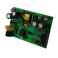
NCP1028LEDGEVB
Description
EVAL BOARD FOR NCP1028LEDG
Manufacturer
ON Semiconductor
Specifications of NCP1028LEDGEVB
Design Resources
NCP1028LEDGEVB BOM CP1028LEDGEVB Gerber Files NCP1028LED EVB Schematic
Current - Output / Channel
720mA
Outputs And Type
1, Isolated
Voltage - Output
18V
Voltage - Input
90 ~ 265VAC
Utilized Ic / Part
NCP1028
Core Chip
NCP1028
Topology
Flyback
No. Of Outputs
1
Output Current
720mA
Output Voltage
18V
Development Tool Type
Hardware - Eval/Demo Board
Leaded Process Compatible
Yes
Mcu Supported Families
NCP1028
Rohs Compliant
Yes
Lead Free Status / RoHS Status
Lead free / RoHS Compliant
Features
-
Lead Free Status / Rohs Status
Lead free / RoHS Compliant
For Use With/related Products
NCP1028LEDG
Other names
NCP1028LEDGEVBOS


36 mW in nominal high-line operation. Figure 29b
simulation result confirms our calculations.
condition. Please note that output pulses only reappear
wire a filtering capacitor between BO and GND (close to
the circuit) to avoid adversely triggering the internal latch
(unless this is a wanted feature) when the pulse train
appears.
Latchoff Protection
fully turned-off and stay latched. This can happen in the
The bridge power dissipation is 330
Figure 30 describes signal variations during a brown-out
Depending on input surge tests, it might be necessary to
There are some situations where the converter shall be
Figure 30. Signal Evolution During a Brown-Out Condition
2
/3.018 Meg =
http://onsemi.com
NCP1028
17
when V
sequence. As in fault mode conditions, the startup source
is activated on and off and self-supplies the controller in a
Dynamic Self-Supply (DSS) mode.
presence of a secondary overvoltage (the feedback loop is
drifting) or when an overtemperature is detected.
Secondary monitoring is usually implemented when the
coupling between auxiliary and power windings does not
lead to a precise primary detection. Due to the addition of
a comparator on the BO pin, a simple external circuit can
lift up this pin above VLATCH and permanently disable
pulses. The V
typically to reset the controller.
CC
reaches V
CC
needs to be cycled down below 3.5 V
CC(ON)
, ensuring a clean startup
Related parts for NCP1028LEDGEVB
Image
Part Number
Description
Manufacturer
Datasheet
Request
R

Part Number:
Description:
Low Dropout Linear Regulator Controller
Manufacturer:
ON Semiconductor
Datasheet:

Part Number:
Description:
EVAL BOARD FOR NCP102MBG
Manufacturer:
ON Semiconductor
Datasheet:
Part Number:
Description:
ON Semiconductor [VOLTAGE REGULATOR]
Manufacturer:
ON Semiconductor
Datasheet:
Part Number:
Description:
357-036-542-201 CARDEDGE 36POS DL .156 BLK LOPRO
Manufacturer:
ON Semiconductor
Datasheet:
Part Number:
Description:
357-036-542-201 CARDEDGE 36POS DL .156 BLK LOPRO
Manufacturer:
ON Semiconductor
Datasheet:
Part Number:
Description:
357-036-542-201 CARDEDGE 36POS DL .156 BLK LOPRO
Manufacturer:
ON Semiconductor
Datasheet:
Part Number:
Description:
357-036-542-201 CARDEDGE 36POS DL .156 BLK LOPRO
Manufacturer:
ON Semiconductor
Datasheet:
Part Number:
Description:
357-036-542-201 CARDEDGE 36POS DL .156 BLK LOPRO
Manufacturer:
ON Semiconductor
Datasheet:
Part Number:
Description:
357-036-542-201 CARDEDGE 36POS DL .156 BLK LOPRO
Manufacturer:
ON Semiconductor
Datasheet:
Part Number:
Description:
357-036-542-201 CARDEDGE 36POS DL .156 BLK LOPRO
Manufacturer:
ON Semiconductor
Datasheet:
Part Number:
Description:
357-036-542-201 CARDEDGE 36POS DL .156 BLK LOPRO
Manufacturer:
ON Semiconductor
Datasheet:
Part Number:
Description:
357-036-542-201 CARDEDGE 36POS DL .156 BLK LOPRO
Manufacturer:
ON Semiconductor
Datasheet:
Part Number:
Description:
357-036-542-201 CARDEDGE 36POS DL .156 BLK LOPRO
Manufacturer:
ON Semiconductor
Datasheet:
Part Number:
Description:
Manufacturer:
ON Semiconductor
Datasheet: