MCP1650DM-LED2 Microchip Technology, MCP1650DM-LED2 Datasheet - Page 13
MCP1650DM-LED2
Manufacturer Part Number
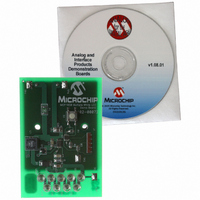
MCP1650DM-LED2
Description
BOARD DEMO FOR MCP1650 WHITE LED
Manufacturer
Microchip Technology
Datasheets
1.MCP1650S-EMS.pdf
(28 pages)
2.MCP1650DM-LED2.pdf
(24 pages)
3.MCP9700T-ELT.pdf
(36 pages)
Specifications of MCP1650DM-LED2
Current - Output / Channel
15mA
Outputs And Type
1, Non-Isolated
Voltage - Output
32.4V
Features
Dimmable
Voltage - Input
2.7 ~ 4.5V
Utilized Ic / Part
MCP1650
Core Chip
MCP1650
Topology
Boost
Output Current
560mA
No. Of Outputs
1
Input Voltage
2.7V To 5.5V
Kit Contents
Board
Development Tool Type
Hardware - Eval/Demo Board
Rohs Compliant
Yes
Lead Free Status / RoHS Status
Contains lead / RoHS non-compliant


© 2005 Microchip Technology Inc.
2.3.2
1. To activate the LEDs, press the push button momentary switch S1. The LEDs
2. The LEDs will be turned off, and the system will enter Sleep mode, when the
2.3.3
The best way to evaluate the MCP1650 Multiple White LED Demo Board is to analyze
the circuit. Measure voltages and currents with a DVM and probe the board with an
oscilloscope.
The firmware program in the PIC10F202 can also be edited to modify the operation of
the application. For example, the subroutine written to generate the different pulse
widths can be changed to suit the needs of various applications with different
intensities.
Typical Example
Let’s consider a practical application for driving nine white LEDs with the MCP1650
using a three-cell Li-Ion input.
R
2.3.4
Since a high boost ratio is needed, the boost regulator will operate in Discontinuous
Current mode. Therefore, the energy going into the inductor every switching cycle must
be greater than the energy needed to supply the load for that switching cycle. The con-
servative efficiency estimate of 80% was chosen to provide margin so that the boost
regulator will operate in Discontinuous Current mode.
SENSE
turn on at full intensity level when the push button is pressed, changing intensity
when the push button is pressed again. There are 3 levels of 100%, 50% and
25% LED intensities (plus the “OFF” state). The input is fused for overcurrent
protection. The intensity of the LEDs are controlled via the SHDN input pin of
MCP1650. A pulse width modulated (PWM) signal is generated by the
PIC10F202 and routed to the SHDN pin of the MCP1650. The MCP1650 is
actually pulsed, and the duty cycle of the PWM waveform is varied depending on
the intensity required. The narrow pulses create a low intensity while wider
pulses create a high intensity.
LEDs are at 25% intensity state and the push button is pressed. Subsequent
push button presses will cycle the LEDs as described in step1.
Input voltage:
Output voltage:
Output current:
Switching Frequency:
Duty Cycle:
Duty Cycle:
is determined by the following equation:
Activating Application and Changing the LED Intensity
Evaluating the Application
Inductor Selection
2.7V to 4.5V
32.4V (9*V
15 mA
750 kHz
80% for V
56% for V
P
P
P
OUT
OUT
OUT
Installation and Operation
R
IN
IN
F
SENSE
)
< 3.8V
> 3.8V
=
=
=
V
32.4V 15mA
0.486 watts
OUT
=
----------- -
I
V
OUT
FB
I
OUT
DS51586A-page 9
Related parts for MCP1650DM-LED2
Image
Part Number
Description
Manufacturer
Datasheet
Request
R

Part Number:
Description:
BOARD DEMO FOR MCP1650 SEPIC
Manufacturer:
Microchip Technology
Datasheet:

Part Number:
Description:
BOARD DEMO FOR MCP165X
Manufacturer:
Microchip Technology
Datasheet:

Part Number:
Description:
Manufacturer:
Microchip Technology Inc.
Datasheet:
Part Number:
Description:
Manufacturer:
Microchip Technology Inc.
Datasheet:
Part Number:
Description:
Manufacturer:
Microchip Technology Inc.
Datasheet:
Part Number:
Description:
Manufacturer:
Microchip Technology Inc.
Datasheet:
Part Number:
Description:
Manufacturer:
Microchip Technology Inc.
Datasheet:
Part Number:
Description:
Manufacturer:
Microchip Technology Inc.
Datasheet:
Part Number:
Description:
Manufacturer:
Microchip Technology Inc.
Datasheet:
Part Number:
Description:
Manufacturer:
Microchip Technology Inc.
Datasheet: