IRPLLED1 International Rectifier, IRPLLED1 Datasheet - Page 6
IRPLLED1
Manufacturer Part Number
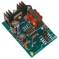
IRPLLED1
Description
BOARD EVALUATION FOR IRS2540PBF
Manufacturer
International Rectifier
Specifications of IRPLLED1
Current - Output / Channel
1.5A
Outputs And Type
1, Non-Isolated
Voltage - Output
24V
Features
Dimmable
Voltage - Input
50 ~ 170V
Utilized Ic / Part
IRS2540PBF
Core Chip
IRS2540, IRS2541, IRS25401
Topology
Buck (Step Down)
No. Of Outputs
1
Output Current
1.5A
Output Voltage
500mV
Dimming Control Type
PWM
Development Tool Type
Hardware - Eval/Demo Board
Lead Free Status / RoHS Status
Contains lead / RoHS compliant by exemption


The frequency in the IRS2540/1/01/11 application is free running and maintains current regulation by quickly
adapting to changes in input and output voltages. There is no need for additional external components to set the
frequency as seen in other controllers. The frequency is determined by L1 and COUT, as well as the input/output
voltages and load current. The selection of the frequency is a trade-off between system efficiency, current control
regulation, size, and cost.
The higher the frequency, the smaller and lower the cost of L1 and COUT, the higher the ripple, the higher the FET
switching losses, which becomes the driving factor as VBUS increases to higher voltages, the higher the component
stresses and the harder it is to control the output current.
In order to maintain good output current regulation with minimum ripple, the value of L1 needs to be adequately
sized. COUT is optional and can also be used for energy storage, which allows the converter to run at a lower
frequency. Excess ripple at the output results in high peak currents that are undesirable for driving high power LEDs
and also negates the ability of the system to accurately regulate the average current.
First, the effect of the inductor in a configuration with no output capacitor will be considered to clearly demonstrate
the impact of the inductor. In this case, the load current is identical to the inductor current. Fig. 7 shows how the
inductor value influences the frequency over a range of input voltages. As can be seen, the input voltage also has a
great effect on the frequency. The inductor value reduces the frequency for lower input voltages.
www.irf.com
3. Frequency selection
4. Output L1 and COUT selection
1600
1400
1200
1000
800
600
400
200
0
10
Fig. 6 Vbus = 100V, L1 = 470uH, COUT = 33uF
15
RD-0608
Vout (V)
20
25
±0.1%
±0.17%
±0.13%
±0.25%
350mA
700mA
1A
1.5A
30
6
Related parts for IRPLLED1
Image
Part Number
Description
Manufacturer
Datasheet
Request
R

Part Number:
Description:
SCHOTTKY RECTIFIER
Manufacturer:
International Rectifier Corp.
Datasheet:
Part Number:
Description:
SCHOTTKY RECTIFIER
Manufacturer:
International Rectifier Corp.
Datasheet:
Part Number:
Description:
SCHOTTKY RECTIFIER
Manufacturer:
International Rectifier Corp.
Datasheet:
Part Number:
Description:
SCHOTTKY RECTIFIER
Manufacturer:
International Rectifier Corp.
Datasheet:
Part Number:
Description:
SCHOTTKY RECTIFIER
Manufacturer:
International Rectifier Corp.
Datasheet:
Part Number:
Description:
SCHOTTKY RECTIFIER
Manufacturer:
International Rectifier Corp.
Datasheet:
Part Number:
Description:
SCHOTTKY RECTIFIER
Manufacturer:
International Rectifier Corp.
Datasheet:
Part Number:
Description:
SCHOTTKY RECTIFIER
Manufacturer:
International Rectifier Corp.
Datasheet:
Part Number:
Description:
SCHOTTKY RECTIFIER
Manufacturer:
International Rectifier Corp.
Datasheet:
Part Number:
Description:
SCHOTTKY RECTIFIER
Manufacturer:
International Rectifier Corp.
Datasheet:
Part Number:
Description:
SCHOTTKY RECTIFIER
Manufacturer:
International Rectifier Corp.
Datasheet:
Part Number:
Description:
SCHOTTKY RECTIFIER
Manufacturer:
International Rectifier Corp.
Datasheet:
Part Number:
Description:
SCHOTTKY RECTIFIER
Manufacturer:
International Rectifier Corp.
Datasheet:
Part Number:
Description:
SCHOTTKY RECTIFIER
Manufacturer:
International Rectifier Corp.
Datasheet:
Part Number:
Description:
SCHOTTKY RECTIFIER
Manufacturer:
International Rectifier Corp.
Datasheet: