LM3402HVEVAL National Semiconductor, LM3402HVEVAL Datasheet

BOARD EVALUATION FOR LM3402HV

LM3402HVEVAL

Manufacturer Part Number
LM3402HVEVAL
Description
BOARD EVALUATION FOR LM3402HV
Manufacturer
National Semiconductor
Series
PowerSmart®r
Datasheets

Specifications of LM3402HVEVAL

Current - Output / Channel
500mA
Outputs And Type
1, Non-Isolated
Voltage - Output
4 V
Features
Dimmable
Voltage - Input
6 ~ 75 V
Utilized Ic / Part
LM3402
Core Chip
LM3402HV
Topology
Buck
Input Voltage
6V To 75V
Dimming Control Type
PWM
Kit Contents
Board
Svhc
No SVHC (15-Dec-2010)
Kit Features
Cycle-by-Cycle Current Limit, Separate PWM Dimming
Lead Free Status / RoHS Status
Lead free / RoHS Compliant
Other names
*LM3402HVEVAL
© 2007 National Semiconductor Corporation
LM3402/02HV Demo Board
Introduction
The LM3402/LM3402HV is a buck regulator derived con-
trolled current source designed to drive a series string of high
power, high brightness LEDs (HBLEDs) such as the Lux-
eon™ I Emitter at forward currents of up to 500 mA. The board
can accept an input voltage ranging from 6V to 42V when
using the LM3402. When using the pin-for-pin compatible
LM3402HV the upper bound of input voltage is 75V. The con-
verter output voltage adjusts as needed to maintain a con-
stant current through the LED array. The LM3402/02HV is a
true step-down regulator with an output voltage range ex-
tending from a V
V
It can maintain regulated current through any number of LEDs
as long as the combined forward voltage of the array does not
exceed V
Circuit Performance LM3402
The LM3402 circuit and BOM have been designed to provide
a constant forward current of 350 mA to a single LED with a
forward voltage of approximately 3.5V. (Typical of white, blue,
and green LEDs using InGaN technology.) When powered
from a 24V ±5% input the demo board will maintain the aver-
age LED current, I
current, Δi
frequency for the demo board is 600 kHz ± 10% over the input
voltage range of 6V to 42V.
Circuit Performance LM3402HV
The LM3402HV circuit and BOM have been designed to pro-
vide a constant forward current of 350 mA to a single LED
with a forward voltage of approximately 3.5V. When powered
from a 48V ± 5% input the demo board will maintain I
±5% of 350 mA. Ripple current will not exceed 70 mA peak-
to-peak. Switching frequency for the demo board is 250 kHz
±10% over the input voltage range of 6V to 75V.
Connecting to LED Array
The LM3402/02HV demo board includes a female 6-pin SIP,
J1, connector as well as two standard 94mil turret connectors
for the cathode and anode connections of the LED array. Fig-
ure 1 shows the pinout of J1. Solid, 18 or 20 gauge wire with
about 1 cm of insulation stripped away makes a convenient,
solderless connection to J1.
O(MAX)
determined by the minimum off time (typically 300 ns).
O(MAX).
F
, will not exceed 70 mA peak-to-peak. Switching
.
O(MIN)
F
, to within 10% of 350 mA. The ripple
of 200 mV (the reference voltage) to a
201980
F
to within
National Semiconductor
Application Note 1500
Chris Richardson
June 2007
Setting the LED Current
The default forward current I
350 mA, typical of many 1W LEDs. To adjust this value the
current setting resistor R
following equation:
This resistor should be rated to handle the power dissipation
of the LED current. For example, the closest 5% tolerance
resistor to set an LED current of 350 mA is 0.56 Ω. In steady
state this resistor will dissipate (0.352 x 0.56) = 69 mW, indi-
cating that a resistor with a 1/8W power rating is appropriate.
PWM Dimming
The DIM1 terminal on the PCB provides an input for a pulse
width modulation signal for dimming of the LED array. In order
to fully enable and disable the LM3402/02HV the PWM signal
should have a maximum logic low level of 0.8V and a mini-
mum logic high level of 2.2V. The maximum PWM dimming
frequency, minimum PWM duty cycle and maximum duty cy-
cle are illustrated in Figure 2. PWM frequency should be at
least one order of magnitude below the LM3402/02HV switch-
ing frequency. The interval t
logic high at the DIM pin to the onset of the output current.
The quantities t
output current to slew up to steady state and slew down to
zero, respectively. Typical response times for the standard
LM3402 and LM3402HV demo boards circuits are shown in
the Typical Performance Characteristics section.
SU
and t
t
SD
SNS
SNS
FIGURE 1.
represent the time needed for the
= 220 ns
LED
can be changed according to the
D
represents the delay from a
delivered to the LED array is
20198001
www.national.com

Related parts for LM3402HVEVAL

LM3402HVEVAL Summary of contents

Page 1

... LED array. Fig- ure 1 shows the pinout of J1. Solid gauge wire with about insulation stripped away makes a convenient, solderless connection to J1. © 2007 National Semiconductor Corporation National Semiconductor Application Note 1500 Chris Richardson June 2007 ...

Page 2

The logic of DIM1 is direct, hence the LM3402/02HV will de- liver regulated output current when the voltage at DIM1 is high, and the current output is disabled when the voltage at DIM1 is low. Connecting a constant logic low ...

Page 3

ID Part Number U1 LM3402 L1 SLF10145T-101M1R0 D1 CMSH1-60M Cf VJ0805Y104KXXAT Cb VJ0805Y103KXXAT Cin C3216X7R1H105M Rsns ERJ6BQFR56V Ron CRCW08054642F Rz CRCW08050R00F DIM1, DIM2 160-1512 GND1, GND2, 160-1026 GND3, VIN, ISNS / 535676-5 FIGURE 3. ...

Page 4

ID Part Number U1 LM3402HV L1 SLF10145T-151MR79 D1 CMSH1-100M Cf VJ0805Y104KXXAT Cb VJ0805Y103KXXAT Cin C3225X7R2A105M Co1 C3216X7R1E225M Rsns ERJ6BQFR68V Ron CRCW08051303F Rz CRCW08050R00F DIM1, DIM2 160-1512 GND1, GND2, 160-1026 GND3, VIN, ISNS / 535676-5 ...

Page 5

Typical Performance Characteristics Efficiency for Table 25° 350 for Table 25°C A DIM Pin Enable Table 1 Efficiency for Table 25°C, ...

Page 6

Switching Waveforms for Table 1 DIM Pin Enable Table 2 Switching Waveforms for Table 2 www.national.com Output Ripple Current Table 1 20198014 DIM Pin Disable Table 2 20198016 Output Ripple Current Table 2 20198018 6 20198015 20198017 20198019 ...

Page 7

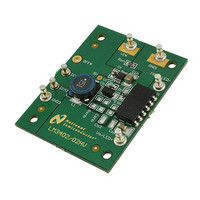
Layout Top Layer and Top Overlay 7 20198006 www.national.com ...

Page 8

Bottom Layer and Bottom Overlay 8 20198007 ...

Page 9

Notes 9 www.national.com ...

Page 10

... National Semiconductor and the National Semiconductor logo are registered trademarks of National Semiconductor Corporation. All other brand or product names may be trademarks or registered trademarks of their respective holders. ...

Related keywords