LM3402HVEVAL National Semiconductor, LM3402HVEVAL Datasheet - Page 2
LM3402HVEVAL
Manufacturer Part Number
LM3402HVEVAL
Description
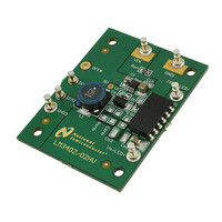
BOARD EVALUATION FOR LM3402HV
Manufacturer
National Semiconductor
Series
PowerSmart®r
Specifications of LM3402HVEVAL
Current - Output / Channel
500mA
Outputs And Type
1, Non-Isolated
Voltage - Output
4 V
Features
Dimmable
Voltage - Input
6 ~ 75 V
Utilized Ic / Part
LM3402
Core Chip
LM3402HV
Topology
Buck
Input Voltage
6V To 75V
Dimming Control Type
PWM
Kit Contents
Board
Svhc
No SVHC (15-Dec-2010)
Kit Features
Cycle-by-Cycle Current Limit, Separate PWM Dimming
Lead Free Status / RoHS Status
Lead free / RoHS Compliant
Other names
*LM3402HVEVAL


www.national.com
The logic of DIM1 is direct, hence the LM3402/02HV will de-
liver regulated output current when the voltage at DIM1 is
high, and the current output is disabled when the voltage at
DIM1 is low. Connecting a constant logic low will disable the
output, and the LM3402/02HV is enabled if the DIM pin is
open-circuited. The DIM1 function disables only the power
NFET, leaving all other circuit blocks functioning to minimize
the converter response time.
The DIM2 terminal provides a second method for PWM dim-
ming by connecting to the gate of an optional NFET, Q1. Note
that Q1 is not provided on the standard BOM, and must be
added for the DIM2 function to operate. Q1 provides a parallel
path for the LED current. This small NFET can be turned on
and off much more quickly than the LM3402/02HV can shut-
down the internal NFET, providing faster response time for
higher frequency and/or greater resolution in the PWM dim-
ming signal. The tradeoff in this method is that the full current
flows through Q1 while the LED is off, resulting in lower effi-
ciency.
The logic of DIM2 is inverted, hence the LM3402/02HV will
deliver regulated output current when the voltage at DIM2 is
low, and the current output is disabled when the voltage at
DIM2 is high. Connecting a constant logic high to the DIM2
will turn off the LED but will not shut down the LM3402/02HV.
FIGURE 2. PWM Dimming Limits
2
Low Power Shutdown
The LM3402/02HV can be placed into a low power shutdown
(typically 90 µA) by grounding the OFF* terminal. During nor-
mal operation this terminal should be left open-circuit.
Output Open Circuit
With either DIM terminal floating or connected to logic high,
the LM3402/02HV will begin to operate as soon as it has an
input of at least 6V. In the case that the input is powered but
no LED array is connected the output voltage will rise to equal
the input voltage. The output of the circuit is rated to 50V
(LM3402) or 100V (LM3402HV) and will not suffer damage,
however care should be taken not to connect an LED array if
the output voltage is higher than the target forward voltage of
the LED array in steady state. Alternatively, a zener diode and
zener current limiting resistor can be placed in the positions
Z1 and R
output Z1 will enter reverse bias and attempt to pull the CS
pin voltage up to the output voltage. An internal comparator
monitors the CS pin voltage and will disable the internal NFET
in this case. The result is a low power hiccup mode, designed
to prevent excessive voltage at the output and thermal stress
on the inductor, internal NFET, and input voltage source.
Z
. In the case of an accidental open circuit at the
20198002
Related parts for LM3402HVEVAL
Image
Part Number
Description
Manufacturer
Datasheet
Request
R

Part Number:
Description:
THREE TERMINAL POSITIVE FIXED VOLTAGE REGULATORS
Manufacturer:
Motorola Inc
Datasheet:
Part Number:
Description:
Manufacturer:
National Semiconductor Corporation
Datasheet:

Part Number:
Description:
National Semiconductor [8-Bit D/A Converter]
Manufacturer:
National Semiconductor
Datasheet:
Part Number:
Description:
National Semiconductor [Media Coprocessor]
Manufacturer:
National Semiconductor
Datasheet:
Part Number:
Description:
Digitally Controlled Tone and Volume Circuit with Stereo Audio Power Amplifier, Microphone Preamp Stage and National 3D Sound
Manufacturer:
National Semiconductor
Datasheet:
Part Number:
Description:
Digitally Controlled Tone and Volume Circuit with Stereo Audio Power Amplifier, Microphone Preamp Stage and National 3D Sound
Manufacturer:
National Semiconductor
Datasheet:
Part Number:
Description:
AC97 Rev 2 Codec with Sample Rate Conversion and National 3D Sound
Manufacturer:
National Semiconductor