NCP5603GEVB ON Semiconductor, NCP5603GEVB Datasheet
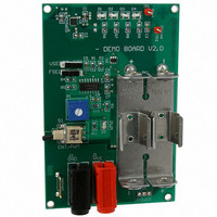
EVAL BOARD FOR NCP5603G HI FREQ

NCP5603GEVB

Manufacturer Part Number
NCP5603GEVB
Description
EVAL BOARD FOR NCP5603G HI FREQ
Manufacturer
ON Semiconductor
Datasheets

Specifications of NCP5603GEVB

Design Resources
NCP5603 EVB BOM NCP5603GEVB Gerber Files NCP5603 EVB Schematic
Current - Output / Channel
160mA
Outputs And Type
1, Non-Isolated
Voltage - Output
4.5 ~ 5 V
Features
Dimmable
Voltage - Input
3V or 3.6V
Utilized Ic / Part
NCP5603
Core Chip
NCP5603
Topology
Charge Pump
No. Of Outputs
1
Development Tool Type
Hardware - Eval/Demo Board
Leaded Process Compatible
Yes
Mcu Supported Families
NCP5603
Rohs Compliant
Yes
Lead Free Status / RoHS Status
Lead free / RoHS Compliant
For Use With/related Products
NCP5603G
Other names
NCP5603GEVBOS
AND8192/D
Charge Pump Based
Multiple LED Driver
Prepared by: Michael Bairanzade
ON Semiconductor
Abstract
system, capable of generating and controlling the power
needed to utilized three features available in modern cellular
phones. In addition to larger displays, with full color
capability, flash and torch features have now been added to
support the embedded camera and the night path finder.
These features are made possible by using an ultra bright
LED powered by standard battery cells.
BASIC CIRCUIT DESCRIPTION
3 V to 4.5 V, depending upon the forward current, a
straightforward connection to a standard battery is not feasible
as depicted Figure 1. A boost structure must be used to make
the power supply voltage compatible with the LED.
December, 2004 − Rev. 0
MB−JUNE 2004
Since the LED have a forward drop voltage ranging from
Semiconductor Components Industries, LLC, 2004
100
This application note describes a multi−functional
90
80
70
60
50
40
30
20
10
0
2
2.5
2.0 X
Figure 1. Typical Lithium−Ion Battery Voltage and White LED
3
Battery Voltage = F(Capacity) @ T
1.5 X
3.5
1
1.33 X
system creates a special case since the converter must be
capable of driving the wide current load needed for the
different functions. The typical currents used to drive the
LED, summarized in Table 1, range from a low 1 mA to
350 mA when the flash is activated. Moreover, unlike the
xenon photo flash, the LED system must have a relatively
long pulse of light to properly illuminate the scene.
Typically, a xenon pulse has a 1 ms flash duration, the LED
system being in the 100 ms to 200 ms range. Consequently,
the converter must be designed to support such a large
demand.
are under development and drivers for these devices should
be available within a few months.
4
On the other hand, combining three functions in the same
High powered LED capable to sustaining up to 800 mA
A
= +20 C
4.5
1.0 X
APPLICATION NOTE
http://onsemi.com
5
OSRAM − LWY87S @10 mA−3.8 V
CITIZEN− CL590S @20 mA−3.9 V
NICHIA−NECWB205 @20 mA−4.0 V
OSRAM − LWT67C @20 mA−4.1 V
Publication Order Number:
Vout (V)
Vout−3 Cell Alkaline
Vout−Li−ion
Vout−2 cell Alkaline
AND8192/D

Related parts for NCP5603GEVB

NCP5603GEVB Summary of contents

Page 1

... AND8192/D Charge Pump Based Multiple LED Driver Prepared by: Michael Bairanzade ON Semiconductor Abstract This application note describes a multi−functional system, capable of generating and controlling the power needed to utilized three features available in modern cellular phones. In addition to larger displays, with full color capability, flash and torch features have now been added to support the embedded camera and the night path finder ...

Page 2

Table 1. White LED Typical Applications LED OSRAM LWY85S OSRAM – LWT67C OSRAM OSRAM – LWW5SG CITIZEN − CL590S NICHIA−NECWB205 LUMILED Along with the amount of current the converter provides worthwhile to note the thermal behavior of both ...

Page 3

C5 10 mF/ LWG6SC D5 TP1 GOLDEN DRAGON D4 LW67C V out D3 LW67C D2 LW67C D1 LW67C C4 1 mF/6 NCP5603 GND C2 1 mF/6 GND CC 4.7 mF/10 ...

Page 4

AND8192/D TOP Layer BOTTOM Layer Figure 3. Printer Circuit Board GERBER Files (scale 1:1) http://onsemi.com 4 ...

Page 5

The system is powered by two AA cells in series, assembled in a standard battery holder, the operating mode being selected by the S1, S5 and S6 switches. Since the total current is limited by the DC/DC converter, the backlights ...

Page 6

... APEM_CMS PUSH_BUT_B CKSWITCH_V TEST_POINT GND_TEST BPACK2 N. American Technical Support: 800−282−9855 Toll Free USA/Canada Japan: ON Semiconductor, Japan Customer Focus Center 2−9−1 Kamimeguro, Meguro−ku, Tokyo, Japan 153−0051 Phone: 81−3−5773−3850 http://onsemi.com 6 Manufacturer Part Number BOURNS 4605X series ...

Related keywords