SOT23-5EV-VREG Microchip Technology, SOT23-5EV-VREG Datasheet - Page 14
SOT23-5EV-VREG
Manufacturer Part Number
SOT23-5EV-VREG
Description
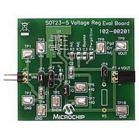
EVAL BOARD SOT23-5 VOLTAGE REG
Manufacturer
Microchip Technology
Datasheet
1.SOT23-5EV-VREG.pdf
(24 pages)
Specifications of SOT23-5EV-VREG
Channels Per Ic
1 - Single
Regulator Type
Positive Fixed & Adjustable
Board Type
Partially Populated
Utilized Ic / Part
SOT-23-5 Package
Silicon Manufacturer
Microchip
Application Sub Type
Voltage Regulator
Kit Application Type
Power Management - Voltage Regulator
Silicon Core Number
MCP1801, MCP1802, TC1014/1015/1185
Lead Free Status / RoHS Status
Lead free / RoHS Compliant
Current - Output
-
Voltage - Output
-
Voltage - Input
-
Operating Temperature
-
Lead Free Status / Rohs Status
Lead free / RoHS Compliant


SOT23-5 Voltage Regulator Evaluation Board User’s Guide
2.3
DS51811A-page 10
GETTING STARTED
The SOT23-5 Voltage Regulator Evaluation Board is fully assembled and tested. All
that is required for operating is a user supplied voltage regulator and a supply voltage
source. Some of the tests that may be completed using the SOT23-5 Voltage Regulator
Evaluation Board shall now be described.
2.3.1
When measuring ground current, jumper JP3 should be removed, otherwise leave
jumper JP3 on. To measure ground current, perform the following steps:
1. Add desired load resistor to R5.
2. Remove jumpers JP3 and JP4.
3. Connect an ammeter across testpoints TP6(+) and TP7(-). Select the
4. Connect a voltmeter across testpoints TP9(+) and TP10(-).
5. Add jumper JP1.
6. Add jumper JP2 to pins 1 and 2.
7. Apply source voltage to testpoints TP1(+) and TP2(-).
8. Verify the voltage across testpoints TP9 and TP10 is within the expected range
9. Read the Ground Current directly from the ammeter connected to testpoints TP6
10. Vary the input voltage to obtain data for ground current versus input voltage.
11. Add the load selection jumper, JP4.
12. Read the Ground Current directly from the ampere meter connected to testpoints
13. The data collected will be the ground current versus load current.
2.3.2
The output voltage of some adjustable voltage regulators may be adjusted by selecting
appropriate resistor divider values connected to the Adjust (ADJ) pin. R2 and R3 pads
are available to be used as the voltage divider.
2.3.3
The Shutdown (SHDN) input selection may be set to V
voltage using testpoint TP5. To select V
pins JP2-1 and JP2-2. To select GND as the SHDN voltage, place a jumper across pins
JP-2 and JP-3. To select a user specified input such as a function generator, remove
the jumper from JP2 and connect the external voltage source positive lead (+) to
testpoint TP5 and the negative lead (-) to testpoint TP4.
appropriate meter scale for the evaluated device.
of the device being tested.
and TP7.
With no load attached to the output of the voltage regulator, the measured ground
current is also called the quiescent current of the regulator.
TP6 and TP7.
Ground Current and Quiescent Current
Adjustable Output Voltage (ADJ)
Shutdown input selection (SHDN)
IN
as the SHDN voltage, place a jumper across
IN
, GND, or a user supplied
© 2009 Microchip Technology Inc.
Related parts for SOT23-5EV-VREG
Image
Part Number
Description
Manufacturer
Datasheet
Request
R


Part Number:
Description:
SOT23/E/ECONRST 3.3V 5% CMOS OUT SOT23 T&R
Manufacturer:
Maxim Integrated Products
Datasheet:
Part Number:
Description:
SOT23-6/A�/20MBPS +3.3V SOT23 RS-485/RS-422 TRANSMITTERS
Manufacturer:
Maxim Integrated Products
Datasheet:
Part Number:
Description:
SOT23-8/A�/Low-Voltage, SOT23, �P Supervisors
Manufacturer:
Maxim Integrated Products
Part Number:
Description:
SOT23/E/ECONORST 3.3V-10% W/PBRST SOT23 T&R
Manufacturer:
Maxim Integrated Products

Part Number:
Description:
SOT23, Low-Power uP Supervisory Circuits with Battery Backup and Chip-Enable Gating
Manufacturer:
Maxim Integrated Products
Datasheet:
Part Number:
Description:
SOT23, Low-Power uP Supervisory Circuits with Battery Backup and Chip-Enable Gating
Manufacturer:
Maxim Integrated Products
