SOT23-5EV-VREG Microchip Technology, SOT23-5EV-VREG Datasheet - Page 15
SOT23-5EV-VREG
Manufacturer Part Number
SOT23-5EV-VREG
Description
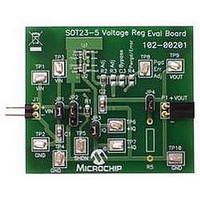
EVAL BOARD SOT23-5 VOLTAGE REG
Manufacturer
Microchip Technology
Datasheet
1.SOT23-5EV-VREG.pdf
(24 pages)
Specifications of SOT23-5EV-VREG
Channels Per Ic
1 - Single
Regulator Type
Positive Fixed & Adjustable
Board Type
Partially Populated
Utilized Ic / Part
SOT-23-5 Package
Silicon Manufacturer
Microchip
Application Sub Type
Voltage Regulator
Kit Application Type
Power Management - Voltage Regulator
Silicon Core Number
MCP1801, MCP1802, TC1014/1015/1185
Lead Free Status / RoHS Status
Lead free / RoHS Compliant
Current - Output
-
Voltage - Output
-
Voltage - Input
-
Operating Temperature
-
Lead Free Status / Rohs Status
Lead free / RoHS Compliant


© 2009 Microchip Technology Inc.
2.3.4
The Power Good (PWRGD) output pin has the ability to be pulled up to either SHDN
or V
PWRGD to be pulled up to V
pull-up resistor causes PWRGD to be pulled up to V
When PWRGD is pulled up to V
active. When PWRGD is pulled up to V
SHDN is active because the current will flow threw R4 and the PWRGD pin to ground.
When low operating currents are critical, PWRGD should be pulled up to V
will keep current consumption at a minimum when SHDN is active because the output
voltage will be low.
2.3.5
R5 is used to set the desired load value. Jumper JP4 is used to connect or disconnect
the load resistance to the output.
2.3.6
Dynamic Line Step response may be evaluated by connecting an electronically
switched input voltage to testpoints TP1(+) and TP2(-) or to connector J1. An
oscilloscope is connected to TP3 (Ch1 Trigger), TP9 (Ch2) and TP10 (GND). An
appropriate load is selected using R5 and JP4. The input voltage is then electronically
switched from a low voltage to a high voltage. The corresponding voltage waveform
data of the voltage regulator response is captured by the oscilloscope. Microchip will
be offering a Line Step module that connects directly to connector J1. The Line Step
module will be capable of switching between two voltage levels that the user supplies
2.3.7
Dynamic Load Step response may be evaluated by connecting an electronically
switched load to testpoints TP9(+) and TP10(-) or to connector P1. An oscilloscope is
connected to the electronic load switch signal (Ch1 Trigger) and to TP9(Ch2) and
TP10(GND). The load is then electronically switched from a high resistance to a low
resistance. The corresponding voltage waveform data of the voltage regulator
response is captured by the oscilloscope. Microchip will be offering a Load Step module
that connects directly to connector P1. The Load Step module will have several
selectable load values populated onboard to cover a wide range of loads. The load will
have the ability to be electronically or manually switched.
2.3.8
Power Supply Rejection Ratio tests are performed by removing the input capacitor
jumper, JP1, and connecting an appropriate PSRR analyzer to the SOT23-5 Voltage
Regulator Evaluation Board. The PSRR analyzer may then sweep the input voltage
frequencies and record the corresponding output voltages.
OUT
. Populating R2 (and removing R4) with the desired pull-up resistor causes
Power Good (PWRGD)
Load Resistance
Line Step
Load Step
Power Supply Rejection Ratio (PSRR)
OUT
OUT
. Populating R4 (and removing R2) with the desired
, the device current will be minimal when SHDN is
IN
, the device current will be higher when when
IN
.
DS51811A-page 11
OUT
. That
Related parts for SOT23-5EV-VREG
Image
Part Number
Description
Manufacturer
Datasheet
Request
R


Part Number:
Description:
SOT23/E/ECONRST 3.3V 5% CMOS OUT SOT23 T&R
Manufacturer:
Maxim Integrated Products
Datasheet:
Part Number:
Description:
SOT23-6/A�/20MBPS +3.3V SOT23 RS-485/RS-422 TRANSMITTERS
Manufacturer:
Maxim Integrated Products
Datasheet:
Part Number:
Description:
SOT23-8/A�/Low-Voltage, SOT23, �P Supervisors
Manufacturer:
Maxim Integrated Products
Part Number:
Description:
SOT23/E/ECONORST 3.3V-10% W/PBRST SOT23 T&R
Manufacturer:
Maxim Integrated Products

Part Number:
Description:
SOT23, Low-Power uP Supervisory Circuits with Battery Backup and Chip-Enable Gating
Manufacturer:
Maxim Integrated Products
Datasheet:
Part Number:
Description:
SOT23, Low-Power uP Supervisory Circuits with Battery Backup and Chip-Enable Gating
Manufacturer:
Maxim Integrated Products
