MCP6V01RD-TCPL Microchip Technology, MCP6V01RD-TCPL Datasheet
MCP6V01RD-TCPL
Specifications of MCP6V01RD-TCPL


Related parts for MCP6V01RD-TCPL

MCP6V01RD-TCPL Summary of contents
Page 1
... PSRR and CMRR. These products operate with a single supply voltage as low as 1.8V, while drawing 300 µA/amplifier (typical) of quiescent current. The Microchip Technology Inc. MCP6V01/2/3 op amps are offered in single (MCP6V01), single with Chip Select (CS) (MCP6V03), and dual (MCP6V02). They are designed in an advanced CMOS process. ...
Page 2
... T = -40 to +125° (Note +85° +125° +85° +125°C A Ω||pF Ω||pF V (Note 1.8V -0.2V to 2.0V CM (Note 1, Note 5.5V -0.2V to 5.7V CM (Note 1, Note 1.8V 0.2V to 1.6V (Note 1) OUT 5.5V 0.2V to 5.3V (Note 1) OUT © 2008 Microchip Technology Inc. ...
Page 3
... These parameters were characterized using the circuit in tone at DC and a residual tone at1 kHz; all other IMD and clock tones are spread by the randomization circuitry includes some uncertainty due to clock edge timing. ODR © 2008 Microchip Technology Inc. = +25° +1.8V to +5.5V and CS = GND (refer to ...
Page 4
... A T -40 — +125 A T -65 — +150 A θ — 44 — °C/W JA θ — 150 — °C GND / and Figure 1-6). Conditions OUT DD – OUT DD = +1.8V to +5.5V GND. SS Conditions °C °C (Note 1) °C (Note 2) © 2008 Microchip Technology Inc. ...
Page 5
... MΩ (typical) FIGURE 1-4: Chip Select (MCP6V03). © 2008 Microchip Technology Inc. 1.4 Test Circuits The circuits used for the DC and AC tests are shown in Figure 1-5 and 1.8V to 5.5V out as discussed in Section 4.3.7 “Supply Bypassing and Filtering” and µ ...
Page 6
... Representative Part +125°C +85°C +25°C -40°C Power Supply Voltage (V) Input Offset Voltage vs CMR_L CMR_H Representative Part +125°C +85°C +25°C -40°C Power Supply Voltage (V) Input Offset Voltage vs CMR_H Representative Part = 1. 5.5V DD Output Voltage (V) Input Offset Voltage vs. © 2008 Microchip Technology Inc. ...
Page 7
... Common Mode Voltage with V = 5.5V. DD 35% 39 Samples T = +25°C 30 5.5V Soldered on PCB DD 25% 20% 15 1/CMRR (µV/V) FIGURE 2-9: CMRR. © 2008 Microchip Technology Inc. = +1.8V to 5.5V GND 14% 40 Samples T = +25°C 12% A Soldered on PCB 10 FIGURE 2-10: 55% 40 Samples 50 +25°C +85°C ...
Page 8
... FIGURE 2-17: Voltage (below / / OUT 105 115 125 Ambient Temperature (°C) Input Bias and Offset +125°C +85°C +25°C -40°C Input Voltage (V) Input Bias Current vs. Input ). SS © 2008 Microchip Technology Inc. ...
Page 9
... – 1. -50 - Ambient Temperature (°C) FIGURE 2-20: Output Voltage Headroom vs. Ambient Temperature. © 2008 Microchip Technology Inc. = +1.8V to 5.5V GND -10 -20 -30 -40 75 100 125 FIGURE 2-21: vs. Power Supply Voltage. 450 400 350 300 250 200 150 100 FIGURE 2-22: Supply Voltage. ...
Page 10
... MCP6V01/2/3 Note: Unless otherwise indicated +25° / kΩ pF, and CS = GND 1.8 1.6 1.4 1.2 1.0 0.8 0.6 0.4 0.2 0.0 -50 - Ambient Temperature (°C) FIGURE 2-24: Power On Reset Voltage vs. Ambient Temperature. DS22058B-page 10 = +1.8V to 5.5V GND 100 125 = OUT DD © 2008 Microchip Technology Inc. ...
Page 11
... -10 -20 -30 1k 10k 100k 1M 1.E+03 1.E+04 1.E+05 1.E+06 Frequency (Hz) FIGURE 2-27: Open-Loop Gain vs. Frequency with V = 5.5V. DD © 2008 Microchip Technology Inc. = +1.8V to 5.5V GND 1.8 1.6 1.4 1.2 1.0 0.8 0.6 0.4 0.2 0.0 -50 100k 1M 1.E+05 1.E+06 FIGURE 2-28: and Phase Margin vs. Ambient Temperature. ...
Page 12
... FIGURE 2-33: = 1.8V. Separation vs. Frequency 0.1 1k 100M 1.0E+08 1.E+03 FIGURE 2-34: = 5.5V. Swing vs. Frequency / / OUT DD RTI 10M 1.E+06 1.E+07 Frequency (Hz) Channel-to-Channel 1.8V DD 10k 100k 1M 1.E+04 1.E+05 1.E+06 Frequency (Hz) Maximum Output Voltage © 2008 Microchip Technology Inc. ...
Page 13
... 5. 100 1k 10k 1.E+02 1.E+03 1.E+04 Frequency (Hz) FIGURE 2-37: Inter-Modulation Distortion vs. Frequency with V Disturbance (see CM Figure 1-7). © 2008 Microchip Technology Inc. = +25° +1.8V to 5.5V 1000 100 IMD tone at DC 100 100k 100 1.E+02 1.E+05 FIGURE 2-38: vs. Frequency with V Figure 1-7). ...
Page 14
... FIGURE 2-45: Step Response 5. FIGURE 2-46: Response / / OUT 5. Time (µs) Non-inverting Small Signal Time (µs) Non-inverting Large Signal Time (µs) Inverting Small Signal Step © 2008 Microchip Technology Inc. ...
Page 15
... Rising Edge 0.7 0.6 0.5 0.4 Falling Edge 0.3 0.2 0.1 0.0 -50 - Ambient Temperature (°C) FIGURE 2-48: Slew Rate vs. Ambient Temperature. © 2008 Microchip Technology Inc. = +1.8V to 5.5V GND 6.0 5 4.0 3.0 2.0 1.0 V 0.0 -1 FIGURE 2-49: vs. Time with G = -100 V/V. ...
Page 16
... Chip Select Voltage (V) Chip Select Current vs. Chip OUT 10 9 Off V Off OUT 1. V kΩ tied Time (5 µs/div) Chip Select Voltage, Output = 1.8V OUT Off V Off OUT 5. V kΩ tied Time (5 µs/div) Chip Select Voltage, Output = 5.5V. DD © 2008 Microchip Technology Inc. ...
Page 17
... Ambient Temperature (°C) FIGURE 2-58: Chip Select Hysteresis 5. 1. -50 - Ambient Temperature (°C) FIGURE 2-59: Chip Select Turn On Time vs. Ambient Temperature. © 2008 Microchip Technology Inc. = +1.8V to 5.5V GND 5. 1. 100 125 -50 -25 FIGURE 2-60: Resistor ( 1.8 Representative Part 1.6 1 ...
Page 18
... Chip Select (CS) Digital Input This pin (CS CMOS, Schmitt-triggered input that places the MCP6V03 op amps into a low power mode of operation. Description ) is 1.8V to 5.5V higher DD ). For normal SS and connected connected to the supply. V will DD DD © 2008 Microchip Technology Inc. ...
Page 19
... The clock is derived from an internal R-C oscillator running at a rate 300 kHz. The oscillator’s OSC1 output is divided down to the desired rate also randomized to minimize (spread) undesired clock tones in the output. © 2008 Microchip Technology Inc. MCP6V01/2/3 4.1 Overview of Auto-zeroing Operation Figure 4-1 shows a simplified diagram of the MCP6V01/2/3 auto-zeroed op amps ...
Page 20
... See ) and very low offset OL Output V OUT Buffer /ΔT ), 1/f noise, and input offset OS A Output V OUT Buffer Figure 2-37 and Figure 2-38. © 2008 Microchip Technology Inc. ...
Page 21
... IN resistors R and R limit the possible current drawn out the input pins. Diodes D and D prevent the input 1 2 © 2008 Microchip Technology Inc. pins (V + and V IN dump any currents onto V shown, resistors R through D and – in nor- IN ...
Page 22
... ISO R ISO V OUT C L MCP6V0X Output Resistor ISO values for ISO G < 10p 100p 1n 10n 100n 1.E-11 1.E-10 1.E-09 1.E-08 1.E-07 C (F) L Recommended R values ISO for your circuit, double check the ISO 's value until the ISO © 2008 Microchip Technology Inc. ...
Page 23
... MCP6V0X to other analog parts FIGURE 4-8: Additional Supply Filtering. © 2008 Microchip Technology Inc. 4.3.8 PCB DESIGN FOR DC PRECISION In order to achieve DC precision on the order of ±1 µV, many physical errors need to be minimized. The design of the Printed Circuit Board (PCB), the wiring, and the thermal environment has a strong impact on the precision achieved ...
Page 24
... Single Difference Amplifier. Note: Changing the orientation of the resistors will usually cause a significant decrease in the cancellation of the thermal voltages and ≈ V ≈ – V – REF REF difference gain neglected OS V OUT REF OUT V REF PCB Layout and Schematic © 2008 Microchip Technology Inc. ...
Page 25
... Dual Non-inverting Amplifier. Note: Changing the orientation of the resistors will usually cause a significant decrease in the cancellation of the thermal voltages. © 2008 Microchip Technology Inc. 4.3.8.5 In cases where an individual resistor needs to have its thermo-junction voltage cancelled, it can be split into Figure 4-14 ...
Page 26
... CMRR. Using a differential input to the ADC helps with the CMRR. 200 Ω µ kΩ 200Ω µF 200Ω kΩ 1 µF 200 Ω FIGURE 4-14: High Performance Design. © 2008 Microchip Technology Inc ADC ½ MCP6V02 V 3 kΩ DD ADC 3 kΩ ½ MCP6V02 ...
Page 27
... HJ voltage at V proportional to T (in °C). The amplifier’ © 2008 Microchip Technology Inc. gain is is set so that V the output of a temperature sensor, which produces a voltage proportional to the temperature (in °C) at the cold junction (T . The W that ...
Page 28
... Use high gain before a comparator to improve the latter’s performance. Do not use MCP6V01/2 comparator by itself; the V not operate properly without a feedback loop integrate FIGURE 4-19 OUT MCP6XXX correction circuitry does OS MCP6V01 kΩ OUT MCP6541 Precision Comparator. © 2008 Microchip Technology Inc. ...
Page 29
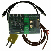
... Helpful links are also provided for Data sheets, Purchase and Sampling of Microchip parts. © 2008 Microchip Technology Inc. MCP6V01/2/3 5.5 Analog Demonstration and Evaluation Boards ...
Page 30
... In the event the full Microchip part number cannot be marked on one line, it will be carried over to the next line, thus limiting the number of available characters for customer-specific information. DS22058B-page 30 Example 6V02 E/MD 0750 256 : Example MCP6VO1E SN 0750 e 3 256 © 2008 Microchip Technology Inc. ...
Page 31
... NOTE 1 TOP VIEW A3 © 2008 Microchip Technology Inc. MCP6V01/2 EXPOSED PAD 2 D2 BOTTOM VIEW A A1 NOTE NOTE 1 DS22058B-page 31 ...
Page 32
... MCP6V01/2/3 N NOTE DS22058B-page φ α c β © 2008 Microchip Technology Inc. ...
Page 33
... Microchip Technology Inc. MCP6V01/2/3 DS22058B-page 33 ...
Page 34
... MCP6V01/2/3 NOTES: DS22058B-page 34 © 2008 Microchip Technology Inc. ...
Page 35
... Figure 4-6) to all circuit ISO diagrams. 5. Added the Typical Performance Curves. 6. Corrected and expanded Information. 7. Minor edits due to change in production status. 8. Added Appendix B, Offset Related Test Screens. Revision A (September 2007) • Original Release of this Document. © 2008 Microchip Technology Inc. Applications MCP6V01/2/3 DS22058B-page 35 ...
Page 36
... CMRR 106 — 1.8V CMRR 116 — 5.5V 114 — 1.8V 122 — 5.5V Table B-1. = GND / 1-6). Conditions = -0.2V to 2.0V (Note -0.2V to 5.7V (Note 0.2V to 1.6V (Note 1) OUT = 0.2V to 5.3V (Note 1) OUT © 2008 Microchip Technology Inc. ...
Page 37
... MCP6V03T Single Op Amp with Chip Select (Tape and Reel for SOIC) Temperature Range -40°C to +125°C Package Plastic Dual Flat, No-Lead (4×4x0.9), 8-lead (MCP6V02 only Plastic SOIC (150mil Body), 8-lead © 2008 Microchip Technology Inc. MCP6V01/2/3 . Examples: a) MCP6V01T-E/SN: Extended temperature, 8LD SOIC package. a) MCP6V02-E/MD: Extended temperature, 8LD 4x4 DFN ...
Page 38
... MCP6V01/2/3 NOTES: DS22058B-page 38 © 2008 Microchip Technology Inc. ...
Page 39
... PowerMate, PowerTool, REAL ICE, rfLAB, Select Mode, Total Endurance, UNI/O, WiperLock and ZENA are trademarks of Microchip Technology Incorporated in the U.S.A. and other countries. SQTP is a service mark of Microchip Technology Incorporated in the U.S.A. All other trademarks mentioned herein are property of their respective companies. ...
Page 40
... Fax: 886-3-572-6459 Taiwan - Kaohsiung Tel: 886-7-536-4818 Fax: 886-7-536-4803 Taiwan - Taipei Tel: 886-2-2500-6610 Fax: 886-2-2508-0102 Thailand - Bangkok Tel: 66-2-694-1351 Fax: 66-2-694-1350 © 2008 Microchip Technology Inc. EUROPE Austria - Wels Tel: 43-7242-2244-39 Fax: 43-7242-2244-393 Denmark - Copenhagen Tel: 45-4450-2828 Fax: 45-4485-2829 France - Paris Tel: 33-1-69-53-63-20 ...