AD8260-EVALZ Analog Devices Inc, AD8260-EVALZ Datasheet - Page 24
AD8260-EVALZ
Manufacturer Part Number
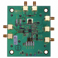
AD8260-EVALZ
Description
BOARD EVAL FOR AD8260
Manufacturer
Analog Devices Inc
Specifications of AD8260-EVALZ
Channels Per Ic
1 - Single
Amplifier Type
Variable Gain
Output Type
Differential
Slew Rate
730 V/µs
-3db Bandwidth
195MHz
Current - Output / Channel
310mA
Operating Temperature
-40°C ~ 105°C
Current - Supply (main Ic)
28.3mA
Voltage - Supply, Single/dual (±)
3.3 V ~ 10 V, ±3.3 V ~ 5 V
Board Type
Fully Populated
Utilized Ic / Part
AD8260
Silicon Manufacturer
Analog Devices
Application Sub Type
Programmable Gain Amplifier
Kit Application Type
Amplifier
Silicon Core Number
AD8260
Kit Contents
Board
Lead Free Status / RoHS Status
Lead free / RoHS Compliant
Lead Free Status / RoHS Status
Lead free / RoHS Compliant, Lead free / RoHS Compliant


AD8260
SINGLE-SUPPLY OPERATION AND AC COUPLING
When operating the AD8260 from a single supply, there are two
bias options for VMDO.
•
•
In both cases, decoupling capacitors are needed on Pin VMDO
to absorb the dynamic currents.
During single-supply operation, the preamplifier input is normally
ac-coupled. An internal bias resistor (nominally 1 k Ω) connected
between PRAI and VMDO provides bias to the preamplifier
input pin. A 50 Ω resistor connected between Pin PRAI and
Pin VMDO, in parallel with the internal 1 kΩ, serves as a termina-
tion resistor and at the same time reduces the offset; the result
is a composite value of about 48 Ω. The VGA input is biased
through the attenuator network and the voltage at Pin VMDO.
When active, the VMID buffer provides the needed bias currents.
When the buffer is disabled, an external voltage is required at
Pin VMDO to provide the bias currents. For example, for a single
5 V application, a reference such as the ADR43 and a stable op
amp provide an adequate 2.5 V VMDO source.
POWER-UP/POWER-DOWN SEQUENCE
For glitch-free power-up operation, the following power-up and
power-down sequence is recommended:
1.
2.
Use an external low impedance midpoint reference at
Pin VMDO and pull VMDI to VNCM to shut down the
VMID buffer.
Use the internal VMID buffer as shown in Figure 64.
Enable the bias by pulling the ENBL pin high. Maintain
GNS0 to GNS3 and TXEN at ground.
It is assumed that after the part wakes up from sleep mode,
the receive section (preamplifier and DGA) needs to be
Rev. A | Page 24 of 32
3.
4.
LOGIC INTERFACES
All logic pins use the same interfaces and, therefore, have the
same behavior and thresholds. The interface contains a Schmitt
trigger type input with a threshold at about 1.1 V and a hystere-
sis of ±0.2 V.
Therefore, the logic low is between ground and 0.8 V, and logic
high is from 1.4 V to VPOS. Because the threshold is so low, the
logic interfaces can be driven directly from 1.8 V or 3.3 V CMOS.
The input bias current is nominally 0.2 μA when the applied
voltage is 3.3 V and 18 nA when grounded.
active first to listen to any signals, and the driver needs to
be off. Therefore, the gain code should be set to 0001 (−6 dB
of gain) first and then the gain adjusted as needed. Note
that any code besides 1 to 11 (binary) disables the receive
section (see Table 4). During receive, it is also important
that the DAC that provides the signal for the high current
driver be disabled to avoid interfering with the received signal.
After receive, presumably data needs to be transmitted via
the high current driver amplifier. At this point, the DAC
should still be off. Pull Pin TXEN high and allow the high
current driver to settle. Enable the DAC. Although the
preamplifier and DGA can remain enabled during the
previous sequence, there may be significant preamplifier
overdrive, and it is best that the receiver be disabled while
transmitting.
Pull Pin ENBL low to disable the chip. To achieve the
specified sleep current of 35 μA, all logic pins must be
pulled low as well.
Related parts for AD8260-EVALZ
Image
Part Number
Description
Manufacturer
Datasheet
Request
R

Part Number:
Description:
High Speed, Low Power Dual Operational Amplifier
Manufacturer:
Analog Devices
Datasheet:

Part Number:
Description:
±1.7g Dual-Axis IMEMS Accelerometer Evaluation Board
Manufacturer:
Analog Devices Inc
Datasheet:

Part Number:
Description:
Inertial Sensor Evaluation System
Manufacturer:
Analog Devices Inc
Datasheet:
Part Number:
Description:
Manufacturer:
Analog Devices Inc
Datasheet:
Part Number:
Description:
Manufacturer:
Analog Devices Inc
Datasheet:
Part Number:
Description:
Manufacturer:
Analog Devices Inc
Datasheet:
Part Number:
Description:
Manufacturer:
Analog Devices Inc
Datasheet:
Part Number:
Description:
Manufacturer:
Analog Devices Inc
Datasheet:
Part Number:
Description:
Manufacturer:
Analog Devices Inc
Datasheet:
Part Number:
Description:
Manufacturer:
Analog Devices Inc
Datasheet:
Part Number:
Description:
Manufacturer:
Analog Devices Inc
Datasheet:
Part Number:
Description:
Manufacturer:
Analog Devices Inc
Datasheet:
Part Number:
Description:
Manufacturer:
Analog Devices Inc
Datasheet: