EVK2160A Atmel, EVK2160A Datasheet - Page 10
EVK2160A
Manufacturer Part Number
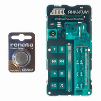
EVK2160A
Description
KIT EVAL FOR AT42QT2160-MMU
Manufacturer
Atmel
Series
Quantum, QTouch™r
Specifications of EVK2160A
Sensor Type
Touch, Capacitive
Sensing Range
8 Buttons/Keys, Slider
Interface
I²C
Voltage - Supply
1.8 V ~ 5.5 V
Embedded
No
Utilized Ic / Part
AT42QT2160
Silicon Manufacturer
Atmel
Silicon Core Number
AT42QT2160-MMU
Kit Application Type
Sensing - Touch / Proximity
Application Sub Type
Capacitive Touch
Kit Contents
Board CD Docs
Rohs Compliant
Yes
Lead Free Status / RoHS Status
Lead free / RoHS Compliant
Sensitivity
-
Lead Free Status / Rohs Status
Supplier Unconfirmed
Other names
427-1141
Available stocks
Company
Part Number
Manufacturer
Quantity
Price
Company:

Part Number:
EVK2160A
Manufacturer:
Atmel
Quantity:
135


4.9.2
4.10
4.10.1
4.10.2
10
PCB Layout, Construction
AT42QT2160
AKS Technology and the Slider
Overview
LED Traces and Other Switching Signals
Key sizes should be in the 5-7mm range when used in the slider to get the best linearity. The
slider should be made up of however many of these elements are required to fit their
dimensions.
The slider will be treated as an object in the Adjacent Key Suppression (AKS) groupings. The
keys in the slider would normally be set to the same burst length and threshold, although
adjustments can be made in these at the expense of linearity.
There can be up to three AKS groups, implemented so that only one key in each group may be
reported as being touched at any one time. The AKS technique will lock onto the dominant key,
and until this key is released, other keys in the group will not be reported as in detection. This
allows a user to slide a finger across multiple keys with only the dominant key reporting touch.
Each key may be in one of the groups 1...3, or in group 0 meaning that it is not AKS enabled.
Keys in the slider are not able to use AKS technique against each other. This is necessary to
enable smooth scrolling. Multiple keys within the slider can be in detect at the same time,
regardless of the AKS settings. The AKS technique will, however, work against keys outside the
object or within another object. For example, if a slider is in the same AKS group as keys, then
touching anywhere on the slider will cause the AKS technique to suppress the keys. Similarly
touching the keys first will suppress the slider.
Note:
It is best to place the chip near the touch keys on the same PCB so as to reduce X and Y trace
lengths, thereby reducing the chances for EMC problems. Long connection traces act as RF
antennae. The Y (receive) lines are much more susceptible to noise pickup than the X (drive)
lines.
Even more importantly, all signal related discrete parts (resistors and capacitors) should be very
close to the body of the chip. Wiring between the chip and the various resistors and capacitors
should be as short and direct as possible to suppress noise pickup.
Ground planes, if used, should be placed under or around the QT chip itself and the associated
resistors and capacitors in the circuit, under or around the power supply, and back to a
connector. Ground planes can be used to shield against radiated noise, but at the expense of a
reduction in sensitivity as described previously.
Note:
Digital switching signals near the Y lines will induce transients into the acquired signals,
deteriorating the SNR performance of the device. Such signals should be routed away from the
Y lines, or the design should be such that these lines are not switched during the course of
signal acquisition (bursts).
For normal operation all keys in the slider should be placed in the same AKS group.
When using ground planes/floods, parasitic capacitance on Y lines can lead to reduced charge-
transfer efficiency. For noise suppression, ground planes/floods can be beneficial around and
between keys on the touch side of the PCB. However, it is advisable to route Y lines on the PCB
layer furthest away from the plane/flood, to reduce parasitic capacitance. Cross-hatched ground
patterns can act as effective shields, while helping to reduce parasitic capacitance. Ground
planes/floods around the chip are generally acceptable, taking into account the same consider-
ations as for the Y line parasitics.
9502A–AT42–07/08
Related parts for EVK2160A
Image
Part Number
Description
Manufacturer
Datasheet
Request
R

Part Number:
Description:
DEV KIT FOR AVR/AVR32
Manufacturer:
Atmel
Datasheet:

Part Number:
Description:
INTERVAL AND WIPE/WASH WIPER CONTROL IC WITH DELAY
Manufacturer:
ATMEL Corporation
Datasheet:
Part Number:
Description:
Low-Voltage Voice-Switched IC for Hands-Free Operation
Manufacturer:
ATMEL Corporation
Datasheet:
Part Number:
Description:
MONOLITHIC INTEGRATED FEATUREPHONE CIRCUIT
Manufacturer:
ATMEL Corporation
Datasheet:
Part Number:
Description:
AM-FM Receiver IC U4255BM-M
Manufacturer:
ATMEL Corporation
Datasheet:
Part Number:
Description:
Monolithic Integrated Feature Phone Circuit
Manufacturer:
ATMEL Corporation
Datasheet:
Part Number:
Description:
Multistandard Video-IF and Quasi Parallel Sound Processing
Manufacturer:
ATMEL Corporation
Datasheet:
Part Number:
Description:
High-performance EE PLD
Manufacturer:
ATMEL Corporation
Datasheet:
Part Number:
Description:
8-bit Flash Microcontroller
Manufacturer:
ATMEL Corporation
Datasheet:
Part Number:
Description:
2-Wire Serial EEPROM
Manufacturer:
ATMEL Corporation
Datasheet: