E6248 Atmel, E6248 Datasheet - Page 10
E6248
Manufacturer Part Number
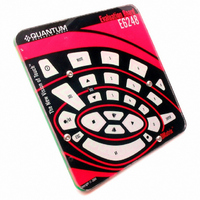
E6248
Description
BOARD EVAL QT60248-AS QMATRIX
Manufacturer
Atmel
Series
Quantum, QMatrix™r
Specifications of E6248
Sensor Type
Touch, Capacitive
Sensing Range
16 / 24 Buttons/Keys
Interface
SPI Serial
Voltage - Supply
3 V ~ 5 V
Embedded
No
Utilized Ic / Part
QT60168, QT60248
Lead Free Status / RoHS Status
Contains lead / RoHS non-compliant
Sensitivity
-
Other names
427-1087


10
USB Connector (J3)
This connector provides direct communications between the E6248 and the PC. It allows full
control over the device including calibration and setups. It also allows for real-time supervision of
signal, reference and calibration information. Uses a standard USB cable (supplied) connected to
a PC.
Matrix Connector (J2)
The E6248 has a header (J2) to allow connection to an external keyboard. The pinout is
described below. The header provides the X-Y scanning of the matrix electrode. X lines drive
charge into the matrix, and the Y lines conduct the charge back out. If an external keyboard is
used it is a good idea to disconnect the on-board matrix. To do that just cut the links to the matrix
(LK1..LK11). Links can be reconnected later by soldering a zero-ohm resistor on the link pads.
Communication Port Select (OPT1)
OPT1 allows the user to switch off the USB chip and communicate directly via the SPI port. The
SPI signal line can be found on J5. The table below shows the different options. If the USB chip
is on, do not use the SPI line as it could damage the evaluation board.
LED Behaviour (OPT2)
OPT2 allows the user to modify LED behaviour, from On/Off to Toggle. See table below.
Pin
Name
State
OPT1
OPT2
GND
1
ON
USB chip on
Latch LED
X7
2
X6
3
OFF
USB chip off – all SPI line are floating
Toggle LED
BOARD DETAILS
X5
4
X4
5
X3
6
X2
7
X1
8
X0
9
GND
10
Y2
11
Y1
12
13
Y0
GND
14
Related parts for E6248
Image
Part Number
Description
Manufacturer
Datasheet
Request
R

Part Number:
Description:
DEV KIT FOR AVR/AVR32
Manufacturer:
Atmel
Datasheet:

Part Number:
Description:
INTERVAL AND WIPE/WASH WIPER CONTROL IC WITH DELAY
Manufacturer:
ATMEL Corporation
Datasheet:
Part Number:
Description:
Low-Voltage Voice-Switched IC for Hands-Free Operation
Manufacturer:
ATMEL Corporation
Datasheet:
Part Number:
Description:
MONOLITHIC INTEGRATED FEATUREPHONE CIRCUIT
Manufacturer:
ATMEL Corporation
Datasheet:
Part Number:
Description:
AM-FM Receiver IC U4255BM-M
Manufacturer:
ATMEL Corporation
Datasheet:
Part Number:
Description:
Monolithic Integrated Feature Phone Circuit
Manufacturer:
ATMEL Corporation
Datasheet:
Part Number:
Description:
Multistandard Video-IF and Quasi Parallel Sound Processing
Manufacturer:
ATMEL Corporation
Datasheet:
Part Number:
Description:
High-performance EE PLD
Manufacturer:
ATMEL Corporation
Datasheet:
Part Number:
Description:
8-bit Flash Microcontroller
Manufacturer:
ATMEL Corporation
Datasheet:
Part Number:
Description:
2-Wire Serial EEPROM
Manufacturer:
ATMEL Corporation
Datasheet: