STEVAL-MKI032V1 STMicroelectronics, STEVAL-MKI032V1 Datasheet - Page 11
STEVAL-MKI032V1
Manufacturer Part Number
STEVAL-MKI032V1
Description
BOARD DEMO ACCELEROMETER DIL24
Manufacturer
STMicroelectronics
Series
MEMSr
Specifications of STEVAL-MKI032V1
Design Resources
STEVAL-MKI032V1 Schematic STEVAL-MKI032V1 Gerber Files STEVAL-MKI032V1 Bill of Materials
Sensor Type
Accelerometer, 3 Axis
Sensing Range
±2.3g, 9.2g
Interface
I²C, SPI
Sensitivity
18 ~ 72 mg/Digit
Embedded
No
Utilized Ic / Part
STM32 and MEMS Demo Boards
Interface Type
SPI, I2C
For Use With
497-6048 - BOARD EVALUATION FOR STM32
Lead Free Status / RoHS Status
Lead free / RoHS Compliant
Voltage - Supply
-
Lead Free Status / Rohs Status
Lead free / RoHS Compliant
Other names
497-9047


UM0701
5.1.4
The CN13-4-pin of the STM3210B-EVAL is also used by the Tamper button. The Tamper
button cannot be used when using the Int2 signal.
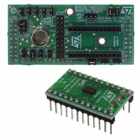
Figure 7.
Setup for digital MEMS - I
Position the JP7 and JP12 jumpers on the STM32-MEMS board.
If Int1 signal is used
Position the JP10 jumper on the STM32-MEMS board.
The CN13-14-pin of the STM3210B-EVAL is also used by the right joystick. If the joystick is
required, remove R75 from the STM3210B-EVAL board.
If Int2 signal is used
Position the JP11 jumper on the STM32-MEMS board.
The CN13-4-pin of the STM3210B-EVAL is also used by the Tamper button. The Tamper
button cannot be used when using the Int2 signal.
Figure 8.
Setup for digital MEMS - SPI interface
Setup for digital MEMS - I
Doc ID 15703 Rev 1
2
C interface
2
C interface
System setup
11/42
Related parts for STEVAL-MKI032V1
Image
Part Number
Description
Manufacturer
Datasheet
Request
R

Part Number:
Description:
BOARD EVAL FOR MEMS SENSORS
Manufacturer:
STMicroelectronics
Datasheet:

Part Number:
Description:
EVALBOARD/STEVAL-ISV014V1
Manufacturer:
STMicroelectronics
Part Number:
Description:
BOARD EVAL FOR ST802RT1
Manufacturer:
STMicroelectronics
Datasheet:

Part Number:
Description:
BOARD EVAL FOR VACUUM CLEANER
Manufacturer:
STMicroelectronics
Datasheet:

Part Number:
Description:
KIT DEV STARTER ST10F276Z5
Manufacturer:
STMicroelectronics
Datasheet:

Part Number:
Description:
BOARD LED CTLR/DVR STLED316S
Manufacturer:
STMicroelectronics
Datasheet:

Part Number:
Description:
BOARD EVAL BLDC SENSORLESS MOTOR
Manufacturer:
STMicroelectronics
Datasheet:

Part Number:
Description:
BOARD ELECT FISCAL CASH REGISTER
Manufacturer:
STMicroelectronics
Datasheet:

Part Number:
Description:
BOARD EVAL BIPO SOLUTION FOR PFC
Manufacturer:
STMicroelectronics
Datasheet:

Part Number:
Description:
BOARD EVAL UPS 450W VOUT=220V
Manufacturer:
STMicroelectronics
Datasheet:
Part Number:
Description:
STMicroelectronics [RIPPLE-CARRY BINARY COUNTER/DIVIDERS]
Manufacturer:
STMicroelectronics
Datasheet:
Part Number:
Description:
STMicroelectronics [LIQUID-CRYSTAL DISPLAY DRIVERS]
Manufacturer:
STMicroelectronics
Datasheet:
Part Number:
Description:
BOARD EVAL FOR MEMS SENSORS
Manufacturer:
STMicroelectronics
Datasheet: