DEMOMPR083 Freescale Semiconductor, DEMOMPR083 Datasheet - Page 7
DEMOMPR083
Manufacturer Part Number
DEMOMPR083
Description
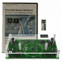
BOARD DEMO FOR MPR083 CTLR
Manufacturer
Freescale Semiconductor
Specifications of DEMOMPR083
Sensor Type
Touch, Capacitive
Sensing Range
8 Buttons/Keys
Interface
I²C
Voltage - Supply
1.8 V ~ 3.6 V
Embedded
Yes, MCU, 8-Bit
Utilized Ic / Part
MPR083
Operating Voltage
1.8 V to 3.6 V
Maximum Operating Temperature
+ 85 C
Minimum Operating Temperature
- 40 C
Operating Current
41 uA
Lead Free Status / RoHS Status
Contains lead / RoHS non-compliant
Sensitivity
-
Lead Free Status / Rohs Status
Lead free / RoHS Compliant
For Use With/related Products
MPR083


Sensors
Freescale Semiconductor
2.3.5 The Slave Address
The MPR083 has a 7-bit long slave address
is low for a write command and high for a read command.
The MPR083 monitors the bus continuously, waiting for a START condition followed by its slave address. When a MPR083
recognizes its slave address, it acknowledges and is then ready for continued communication.
2.3.6
A write to the MPR083 comprises the transmission of the MPR083’s keyscan slave address with the R/W bit set to 0, followed
by at least one byte of information. The first byte of information is the command byte. The command byte determines which
register of the MPR083 is to be written by the next byte, if received. If a STOP condition is detected after the command byte is
received, then the MPR083 takes no further action
command byte are data bytes.
Any bytes received after the command byte are data bytes. The first data byte goes into the internal register of the MPR083
selected by the command byte
If multiple data bytes are transmitted before a STOP condition is detected, these bytes are generally stored in subsequent
MPR083 internal registers because the command byte address generally auto-increments
2.3.7 Message Format for Reading the MPR083
The MPR083 is read using the MPR083’s internally stored command byte as address pointer, the same way the stored command
byte is used as address pointer for a write. The pointer generally auto-increments after each data byte is read using the same
rules as for a write
(Figure
addressed by the initialized command byte.
S
S
12). The master can now read ‘n’ consecutive bytes from the MPR083, with the first data byte being read from the register
Message Format for Writing the MPR083
Command byte is stored on receipt ofSTOP condition
SLAVE ADDRESS
How command byte and data byte
SDA
SCL
(Section
acknowledge from MPR083
map into MPR083's registers
SLAVE ADDRESS
6.4.1). Thus, a read is initiated by first configuring the MPR083’s command byte by performing a write
MSB
R/W
1
acknowledge from MPR083
(Figure
Figure 11. Command and Single Data Byte Received
0
11).
0
A
Figure 10. Command Byte Received
D15 D14 D13 D12 D11 D10 D9
(Figure
R/W
0
Figure 9. Slave Address
(Figure
9). The bit following the 7-bit slave address (bit eight) is the R/W bit, which
0
COMMAND BYTE
10) beyond storing the command byte. Any bytes received after the
A
1
acknowledge from
D7
1
MPR083
D6
D8
D5
0
COMMAND BYTE
A
D4
D7
acknowledge from MPR083
D6
0
D3
(Section
D5
DATA BYTE
D2
D4
R/W
1 byte
2.4).
D3
D1
acknowledge from
D2
ACK
auto-increment memory
D0
MPR083
D1
word address
D0
A
A
MPR083
P
P
7
Related parts for DEMOMPR083
Image
Part Number
Description
Manufacturer
Datasheet
Request
R

Part Number:
Description:
Manufacturer:
STMicroelectronics
Datasheet:

Part Number:
Description:
DEMO BOARD FOR HMC6042/HMC1041Z
Manufacturer:
Honeywell Microelectronics & Precision Sensors

Part Number:
Description:
DEMO BOARD FOR HMC1042L/HMC1041Z
Manufacturer:
Honeywell Microelectronics & Precision Sensors
Datasheet:

Part Number:
Description:
KIT DEMO 4 SENSOR CHAN RS232
Manufacturer:
VTI Technologies
Datasheet:


Part Number:
Description:
DEMO: DC Power Supply, 32 Volts, 3 Amps
Manufacturer:
Tektronix
Part Number:
Description:
DEMO: Programmable DC Power Supply, 32 Volts, 3 Amps
Manufacturer:
Tektronix

Part Number:
Description:
Manufacturer:
Freescale Semiconductor, Inc
Datasheet:
Part Number:
Description:
Manufacturer:
Freescale Semiconductor, Inc
Datasheet:
Part Number:
Description:
Manufacturer:
Freescale Semiconductor, Inc
Datasheet:
Part Number:
Description:
Manufacturer:
Freescale Semiconductor, Inc
Datasheet:
Part Number:
Description:
Manufacturer:
Freescale Semiconductor, Inc
Datasheet:
Part Number:
Description:
Manufacturer:
Freescale Semiconductor, Inc
Datasheet:
Part Number:
Description:
Manufacturer:
Freescale Semiconductor, Inc
Datasheet:
Part Number:
Description:
Manufacturer:
Freescale Semiconductor, Inc
Datasheet: