KITMPR083EVM Freescale Semiconductor, KITMPR083EVM Datasheet - Page 13
KITMPR083EVM
Manufacturer Part Number
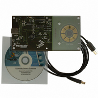
KITMPR083EVM
Description
KIT EVAL 8POSITION ROTARY TOUCH
Manufacturer
Freescale Semiconductor
Specifications of KITMPR083EVM
Sensor Type
Touch, Capacitive
Sensing Range
8 Buttons/Keys
Interface
I²C
Voltage - Supply
1.8 V ~ 3.6 V
Embedded
Yes, Other
Utilized Ic / Part
MPR083
Operating Voltage
1.8 V to 3.6 V
Operating Current
41 uA
Maximum Operating Temperature
+ 85 C
Minimum Operating Temperature
- 40 C
Description/function
Proximity Sensor
Lead Free Status / RoHS Status
Lead free / RoHS Compliant
Sensitivity
-
Lead Free Status / Rohs Status
Lead free / RoHS Compliant
For Use With/related Products
MPR083


Sensors
Freescale Semiconductor
4.3
When in Run1 mode the sensor controller will run continuously. During Run1 all the modules are synchronized by the Master Tick
Period. This value can be set by using the Master Tick Period Register as outlined in the following section.
While in this mode all functionality of the MPR083 is enabled; touch detection will occur, and I
This mode is enabled by setting the Configuration Register’s RUNE and DCE bits high.
4.3.1
The Master Tick Period Register is used to set the master tick of this system. All parts of the system are synchronized to this
counter. This register is overridden in all modes except for Run1. When not in Run1 mode, the value of this register is ignored
and 8ms is used for the primary clock. The I
4.4
When in Run2 mode the sensor controller will continue to scan the electrodes but a low power state will be enabled between
each cycle. Because of this, any I
If DCE is enabled the sensor controller transitions between low power and active states. During the active part of the cycle
communication with the sensor controller is possible; however, Freescale always requires users to issue an ATTN signal prior to
initiating communications. Accessing the I
to produce invalid data.
This mode is enabled by setting the Configuration Register’s RUNE bit high and DCE bit low. The only way to exit this mode is
to toggle the Attention Pin, refer to
4.5
When in Stop1 mode the sensor controller will not scan the electrodes. While capacitance sensing is disabled I
communications will still be accepted and the sensor controller will maintain instantaneous response to all register requests. This
is the only mode in which register values can be set.
This mode is enabled by setting the Configuration Register’s RUNE bit low and DCE bit high.
4.6
When in Stop2 mode the sensor controller will not scan the electrodes or accept I
this mode.
This mode is enabled by setting the Configuration Register’s RUNE bit low and DCE bit low. The only way to exit this mode is to
toggle the Attention Pin, refer to
Table 9. Master Tick Period Register Field Descriptions
Run1 Mode
Master Tick Period Register
Run2 Mode
Stop1 Mode
Stop2 Mode
Reset:
Field
MTP
7:0
W
R
7
0
Section
2
C communication that occurs, may or may not respond while the sensor is in this mode.
Master Tick Period – The Master Tick Period selects or reports the current value of the
touch sensor controller’s primary clock multiplier. The resulting period must be in the
range 5ms to 31ms. If the value is outside of this range the MTP will be set to 00011010.
00000000 Encoding 0 – Sets the primary clock multiplier to 5
~
00011010 Encoding 26 - Sets the primary clock multiplier to 31
Section
= Unimplemented
6
0
4.7.
2
C interface while DCE mode is enabled without sending an ATTN signal first is likely
Figure 16. Master Tick Period Register
4.7.
2
C slave address of the Master Tick Period Register is 0x05.
5
0
4
0
MTP
Description
3
0
2
C communication. The MPR083 is off during
2
1
2
C communication will be available.
1
0
0
1
2
C
MPR083
13
Related parts for KITMPR083EVM
Image
Part Number
Description
Manufacturer
Datasheet
Request
R

Part Number:
Description:
Manufacturer:
Freescale Semiconductor, Inc
Datasheet:
Part Number:
Description:
Manufacturer:
Freescale Semiconductor, Inc
Datasheet:
Part Number:
Description:
Manufacturer:
Freescale Semiconductor, Inc
Datasheet:
Part Number:
Description:
Manufacturer:
Freescale Semiconductor, Inc
Datasheet:
Part Number:
Description:
Manufacturer:
Freescale Semiconductor, Inc
Datasheet:
Part Number:
Description:
Manufacturer:
Freescale Semiconductor, Inc
Datasheet:
Part Number:
Description:
Manufacturer:
Freescale Semiconductor, Inc
Datasheet:
Part Number:
Description:
Manufacturer:
Freescale Semiconductor, Inc
Datasheet:
Part Number:
Description:
Manufacturer:
Freescale Semiconductor, Inc
Datasheet:
Part Number:
Description:
Manufacturer:
Freescale Semiconductor, Inc
Datasheet:
Part Number:
Description:
Manufacturer:
Freescale Semiconductor, Inc
Datasheet:
Part Number:
Description:
Manufacturer:
Freescale Semiconductor, Inc
Datasheet:
Part Number:
Description:
Manufacturer:
Freescale Semiconductor, Inc
Datasheet:
Part Number:
Description:
Manufacturer:
Freescale Semiconductor, Inc
Datasheet:
Part Number:
Description:
Manufacturer:
Freescale Semiconductor, Inc
Datasheet: