AS5030 DB austriamicrosystems, AS5030 DB Datasheet
AS5030 DB
Specifications of AS5030 DB


Related parts for AS5030 DB


AS5030 DB Summary of contents
Page 1
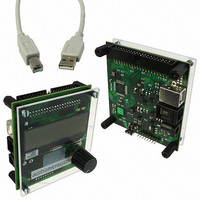
... Jack (>7.5V) if the board works in stand alone mode without any PC. The angle and AGC values are displayed on the LCD screen in both modes. Dimensions of the demo board: 77mm x 84mm (3.03 x 3.30 inch). Figure 1: AS5030 demoboard, TOP side Revision 1.0, 29-May-08 DEMOBOARD OPERATION MANUAL DEMOBOARD AND SOFTWARE OPERATION MANUAL Figure 2: AS5030 demoboard, BOTTOM side www.austriamicrosystems.com Page ...
Page 2
... Getting Started This software allows you to become familiar with the principle of the AS5030 sensor. In order to get started, you need: • The AS5030 Demo Software installer, downloadable on the Austriamicrosystems website • Win-XP® or Windows Vista® operating system • one free USB slot on your PC to connect the demoboard 2 ...
Page 3
... Displays the state of the C2 pin on the selected AS5030. By default (three wires mode). The Lock indicator is the state of the lock bit in the serial stream. This bit should be always enabled. Low Power / Ultra Low Power / Wakeup: Function not yet implemented Revision 1.0, 29-May-08 Figure 4: SSI-Readout tab www.austriamicrosystems.com Page ...
Page 4
... Prog (external mode only): After having written the configuration bits to the AS5030, those bits can be permanently fused by clicking on Prog. After a new power up of the device, this new configuration is enabled. Revision 1.0, 29-May-08 Figure 5: OTP tab www.austriamicrosystems.com Page ...
Page 5
... The U1 switch enables the bootloader mode of the microcontroller, if pressed during power up. In normal mode, pressing the switch makes the microcontroller writing the zero position value into the active AS5030. The connector U7 is used for ISP programming of the microcontroller only. Revision 1.0, 29-May-08 www.austriamicrosystems.com Page ...
Page 6
... Connect to the USB port. 2. Start the software. • Closing the demo software After finishing the work with the demo board the software needs to be closed before disconnecting the demo board. 1. Close the software. 2. Disconnect from the USB port. Revision 1.0, 29-May-08 www.austriamicrosystems.com Page ...
Page 7
... Table of contents 1 General Description........................................................................................................................................................... 1 The AS5030 Demoboard........................................................................................................................................................ 1 2 AS5030 Software............................................................................................................................................................... 2 2.1 Getting Started.......................................................................................................................................................... 2 2.2 Installing the Software .............................................................................................................................................. 2 2.3 Software Usage ........................................................................................................................................................ 2 2.4 SSI-Readout ............................................................................................................................................................. 3 2.5 OTP .......................................................................................................................................................................... 4 3 AS5030 Demoboard hardware .......................................................................................................................................... 5 4 Troubleshooting................................................................................................................................................................. 6 Table of contents........................................................................................................................................................................ 7 Copyrights .................................................................................................................................................................................. 8 Disclaimer................................................................................................................................................................................... 8 Contact Information .................................................................................................................................................................... 8 Revision 1.0, 29-May-08 www.austriamicrosystems.com Page ...
Page 8
... No obligation or liability to recipient or any third party shall arise or flow out of austriamicrosystems AG rendering of technical or other services. ...