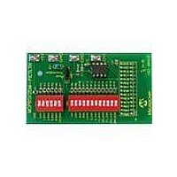
MCP6SX2DM-PCTLTH Microchip Technology, MCP6SX2DM-PCTLTH Datasheet - Page 11

MCP6SX2DM-PCTLTH
Manufacturer Part Number
MCP6SX2DM-PCTLTH
Description
BOARD DEMO PICTAIL THERM MCP6SX2
Manufacturer
Microchip Technology
Series
PICtail™r
Datasheets
1.AC164120.pdf
(36 pages)
2.MCP6SX2DM-PCTLTH.pdf
(32 pages)
3.MCP6SX2DM-PCTLPD.pdf
(12 pages)
Specifications of MCP6SX2DM-PCTLTH
Sensor Type
Thermistor
Interface
Analog
Voltage - Supply
2.5 V ~ 5.5 V
Embedded
No
Utilized Ic / Part
MCP6S22, MCP6S92
Processor To Be Evaluated
MCP6Sx2
Lead Free Status / RoHS Status
Contains lead / RoHS non-compliant
Sensitivity
-
Sensing Range
-
Lead Free Status / Rohs Status
Lead free / RoHS Compliant
Available stocks
Company
Part Number
Manufacturer
Quantity
Price
Company:
Part Number:
MCP6SX2DM-PCTLTH
Manufacturer:
MICROCHIP
Quantity:
12 000
© 2006 Microchip Technology Inc.
1.4.1
The Personal Computer (PC) shown in Figure 1-2 needs to run on Windows
later. It provides a convenient interface for the user, communicates with the other
boards and provides power through the USB connection.
1.4.2
The PICkit™ 1 Signal Analysis PC program configures and programs the PIC16F684
PICmicro
USB port on the PICkit 1 Flash Starter Kit. It also imports data through the same
connection and displays the data in strip-chart, histogram, FFT plot and oscilloscope
plot formats. Data can be output in CSV format for importing into a spreadsheet
program.
1.4.3
The PICkit 1 Flash Starter Kit (DV164101) programs PICmicro microcontrollers. It uses
the PIC16C745’s USB port to communicate with the PICkit 1 Signal Analysis PC
program. It connects to the Signal Analysis PICtail Daughter Board via a header (see
Figure 2-1).
This board provides a single +5V supply voltage for the daughter boards. It can drive
up to 5 µF on the supply; a larger capacitance may interfere with program timing.
1.4.4
This software resides on the PICkit 1 Flash Starter Kit’s PIC16C745 microcontroller.
Use version 2.0.2 or later.
1.4.5
This board is Microchip Development Tool AC164120. It connects to the PICkit 1 Flash
Starter Kit, which it uses for both power and as a communications link to the PC. The
on-board PIC16F684 has a 10-bit ADC which converts the MCP6SX2 PGA Thermistor
PICtail™ Demo Board’s output voltage. The results are temporarily stored on the
board’s 25LC640 serial EEPROM chips.
The +5V single supply voltage from the PICkit 1 Flash Starter Kit board is bypassed
with a bulk 1 µF capacitor and local 0.1 µF capacitors for each IC.
1.4.6
PICA2Dlab.hex is the standard file that supports the PICkit™ 1 Signal Analysis PC
program. The PGA and 10-bit ADC configuration are selected in the Signal Analysis
PC program and written to the PIC16F684. The PIC16F684 then sends the
command(s) over the SPI™ bus to the PGA. It displays the ADC code on the strip chart.
Therm_PGA1.hex implements the first design in AN897. It supports the PICkit™ 1
Signal Analysis PC program, but with reduced functionality; its output can be viewed
on the strip chart only. The results need to be manually converted to commonly-seen
temperature (codes 0 to 1023 convert to 0.0°C to 102.3°C).
Therm_PGA2.hex implements the second design in AN897. It supports the PICkit™ 1
Signal Analysis PC program, but with reduced functionality; its output can be viewed
on the strip chart only. The results need to be manually converted to commonly-seen
temperature (codes 0 to 1023 convert to 0.0°C to 102.3°C).
®
PC Platform
PICkit™ 1 Signal Analysis PC Program
PICkit 1 Flash Starter Kit
PICkit 1 Firmware
Signal Analysis PICtail Daughter Board
Firmware for the Signal Analysis PICtail Daughter Board
microcontroller on the Signal Analysis PICtail Daughter Board through the
DS51517B-page 7
®
98 SE or


