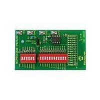
MCP6SX2DM-PCTLTH Microchip Technology, MCP6SX2DM-PCTLTH Datasheet - Page 14

MCP6SX2DM-PCTLTH
Manufacturer Part Number
MCP6SX2DM-PCTLTH
Description
BOARD DEMO PICTAIL THERM MCP6SX2
Manufacturer
Microchip Technology
Series
PICtail™r
Datasheets
1.AC164120.pdf
(36 pages)
2.MCP6SX2DM-PCTLTH.pdf
(32 pages)
3.MCP6SX2DM-PCTLPD.pdf
(12 pages)
Specifications of MCP6SX2DM-PCTLTH
Sensor Type
Thermistor
Interface
Analog
Voltage - Supply
2.5 V ~ 5.5 V
Embedded
No
Utilized Ic / Part
MCP6S22, MCP6S92
Processor To Be Evaluated
MCP6Sx2
Lead Free Status / RoHS Status
Contains lead / RoHS non-compliant
Sensitivity
-
Sensing Range
-
Lead Free Status / Rohs Status
Lead free / RoHS Compliant
Available stocks
Company
Part Number
Manufacturer
Quantity
Price
Company:
Part Number:
MCP6SX2DM-PCTLTH
Manufacturer:
MICROCHIP
Quantity:
12 000
MCP6SX2 PGA Thermistor PICtail™ Demo Board User’s Guide
DS51517B-page 10
2.3.1
The standoff and screw listed in Table B-2 are installed at the mounting hole shown in
Figure 2-1. The standoff goes on bottom, and the screw on top.
2.3.2
1. Remove any PICmicro microcontroller that may be in the evaluation socket.
2. Connect the USB cable to the PC and the PICkit 1 Flash Starter Kit board. The
It is easiest to use this board when it lays directly on a bench top.
2.3.3
This board plugs into the PICkit 1 Flash Starter Kit’s expansion header J3 and must not
cover the LED array. There should be no change in the status LEDs on the PICkit 1
Flash Starter Kit board after it is plugged in.
2.3.4
If you would rather use the MCP6S92 PGA, take it out of the anti-static bag and replace
the already installed MCP6S22 PGA.
1. Plug this board into, and directly above, the Signal Analysis PICtail Daughter
2.3.4
1. Select the Real Time Mode radio button.
2. Click on the Strip Chart button.
3. Change the sample speed to 20 Sample/Secs.
4. Click on the green GO button; the strip chart will show the measured output of
5. Change the switch positions (SW
FIGURE 2-2:
status LEDs (green POWER and yellow BUSY in the LED array) should light up.
Board. There should be no change in the status LEDs on the PICkit 1 Flash
Starter Kit board after it is plugged in.
the MCP6SX2 PGA Thermistor PICtail™ Demo Board.
changes. Figure 2-2 shows the result when R
then 12.8 kΩ, and then 217.6 kΩ (see Section 3.2 “Configuring Board”).
Set-up Verification
PCB Standoff
PICkit 1 Flash Starter Kit
Signal Analysis PICtail Daughter Board
MCP6SX2 PGA Thermistor PICtail™ Demo Board
Strip Chart.
1
and SW
2
) and verify that the strip chart
A
was set to 10 kΩ and Rvar to 0Ω,
© 2006 Microchip Technology Inc.


