MCP9800DM-DL Microchip Technology, MCP9800DM-DL Datasheet - Page 14
MCP9800DM-DL
Manufacturer Part Number
MCP9800DM-DL
Description
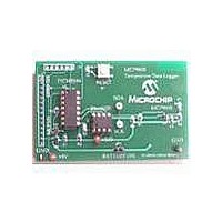
BOARD DEMO FOR MCP9800
Manufacturer
Microchip Technology
Datasheets
1.MCP9800A0T-MOT.pdf
(42 pages)
2.MCP9800A0T-MOT.pdf
(4 pages)
3.MCP9800DM-DL.pdf
(22 pages)
4.MCP9800DM-DL.pdf
(12 pages)
Specifications of MCP9800DM-DL
Sensor Type
Temperature
Sensing Range
-55°C ~ 125°C
Interface
I²C, SMBus
Sensitivity
±0.5°C
Voltage - Supply
2.7 V ~ 5.5 V
Embedded
Yes, MCU, 8-Bit
Utilized Ic / Part
MCP9800
Processor To Be Evaluated
MCP9800
Lead Free Status / RoHS Status
Contains lead / RoHS non-compliant
Lead Free Status / RoHS Status
Lead free / RoHS Compliant, Contains lead / RoHS non-compliant
Available stocks
Company
Part Number
Manufacturer
Quantity
Price

Part Number:
MCP9800DM-DL
Manufacturer:
MICROCHIP/微芯
Quantity:
20 000


2.4
DS51593A-page 10
FUNCTIONAL DESCRIPTION
2.4.1
The
measure ambient temperature using the MCP9800 temperature sensor and store the
temperature data to the 24LC1025 serial EEPROM. The number of samples and the
sampling duration is specified by the user. Once the specified number of samples are
stored, the controller waits for a command from the PICkit™ 1 Flash Starter Kit signal
analysis tool to transmit the samples to the PC. The software tool can be used to save
the data in *.csv format, which allows the user to view the data using Microsoft Excel
software.
There are two LEDs on-board, D
turns on when the ambient temperature rises above the user specified limit and it
remains lit until the temperature falls below the user specified hysteresis limit. (see
Section 2.4.2.3). D
sampling temperature. During this time, it turns on momentarily every time temperature
is sampled. Once all samples are acquired, D
The RESET switch, S1, is used to reset the PICmicro microcontroller. Clicking GO in
the signal analysis software also resets the PICmicro microcontroller.
There are three sources of power connections to the data logger. Power can be sup-
plied by connecting the 14-pin header to the PICKit™ 1 Flash Starter Kit board. The
user can also connect a +5V supply using the on-board test points. In addition, this
board supports a 24 mm 3V Lithium cell for stand-alone operation. To use the battery,
the “Battery On” jumper JP1 will need to be connected.
In order to prevent power contention between the power supply and on-board battery,
a dual Schottky diode, U5, is used to limit the current path. The diode ensures normal
operation if the board is connected to a +5V supply, while the Battery On jumper is
connected. There is about a 100 mV (typical) drop across the Schottky diode. The out-
put of the diode is referred to as V
The MCP9800 Temperature Data Logger Demo board also uses Microchip’s MCP101
supervisor to reset the controller if V
MCP9800 Temperature Data Logger Demo board
The MCP9800 Temperature Data Logger Demo board
2
indicates that the PICmicro microcontroller is in the process of
1
DD
and D
DD
.
drifts below 2.5V.
2
. D
1
2
indicates an overtemperature alert. It
will remain off.
© 2005 Microchip Technology Inc.
uses the PIC16F684 to
Related parts for MCP9800DM-DL
Image
Part Number
Description
Manufacturer
Datasheet
Request
R

Part Number:
Description:
Manufacturer:
Microchip Technology, Inc.
Datasheet:

Part Number:
Description:
(MCP9800 - MCP9803) 2-Wire High-Accuracy Temperature Sensor
Manufacturer:
Microchip Technology
Datasheet:

Part Number:
Description:
Manufacturer:
Microchip Technology Inc.
Datasheet:
Part Number:
Description:
Manufacturer:
Microchip Technology Inc.
Datasheet:
Part Number:
Description:
Manufacturer:
Microchip Technology Inc.
Datasheet:
Part Number:
Description:
Manufacturer:
Microchip Technology Inc.
Datasheet:
Part Number:
Description:
Manufacturer:
Microchip Technology Inc.
Datasheet:
Part Number:
Description:
Manufacturer:
Microchip Technology Inc.
Datasheet:
Part Number:
Description:
Manufacturer:
Microchip Technology Inc.
Datasheet:
Part Number:
Description:
Manufacturer:
Microchip Technology Inc.
Datasheet: