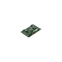
ATAVRXPLAIN Atmel, ATAVRXPLAIN Datasheet - Page 7

ATAVRXPLAIN
Manufacturer Part Number
ATAVRXPLAIN
Description
KIT EVAL FOR ATXMEGA128A1
Manufacturer
Atmel
Series
AVR® XMEGAr
Type
MCUr
Specifications of ATAVRXPLAIN
Contents
Board
Silicon Manufacturer
Atmel
Core Architecture
AVR
Silicon Core Number
ATmega128A1
Silicon Family Name
AVR XMEGA
Kit Contents
Board
Rohs Compliant
Yes
For Use With/related Products
ATXMEGA128A1
Lead Free Status / RoHS Status
Lead free / RoHS Compliant
Available stocks
Company
Part Number
Manufacturer
Quantity
Price
Company:
Part Number:
ATAVRXPLAIN
Manufacturer:
Atmel
Quantity:
2
2.12 Watchdog
2.13 Brown Out Detector
2.14 JTAG interface and On-Chip Debugging
2.15 Flash and EEPROM Power Reduction Modes
8267B-AVR-12/10
Note that the GPIO registers are defined as volatile, so temporary variables should in
some cases be used when manipulating variables stored in these registers:
Otherwise, the performance gain will be lost.
Use the General Purpose I/O registers for variable storage to minimize power
consumption.
The Watchdog is basically a timer with a separate clock source. It will, if enabled,
contribute to the power consumption in sleep. The watchdog can only be clocked by
the internal 32kHz Ultra Low Power (ULP) oscillator, prescaled to 1kHz.
To minimize the power consumption, disable the Watchdog.
The purpose of the Brown Out Detector (BOD) is to ensure that the device is not
operating at a too low voltage. It is highly recommended to use the internal BOD to
ensure that the device always operates within specification.
However, during sleep the device is “not operating”, or rather, it is not executing code.
For this reason, the BOD can be configured separately for ACTIVE/IDLE and sleep
modes. This allows for the BOD to be enabled only in ACTIVE and IDLE mode. All
configuration of the BOD is done with the device fuses.
To further reduce power consumption, the BOD may be run in sampled mode. The
sample rate is approximately 1kHz, as it is clocked from the prescaled ULP oscillator.
The BOD cannot detect voltage dips between samples in this mode, so it should only
be used in applications with slowly varying operating voltages, such as battery-
powered ones.
Disable the BOD - or better, disable it while in sleep - to reduce power consumption.
Use sampled mode if only slow changes in operating voltage are likely.
The JTAG interface is used for programming and debugging, but has no function
during operation of an end-product. It is clocked and active during sleep if the On-chip
Debugging (OCD) feature is enabled. The OCD and JTAG interface should therefore
be disabled if it is not needed.
The OCD can be disabled in fuses, while the JTAG interface can be disabled both in
fuses and in software. Disabling the JTAG in software ensures that the device can be
reprogrammed because the JTAG interface is re-enabled upon RESET.
Alternatively, the PDI interface can be used for programming and debugging. In this
case the JTAG interface may not be required at all, and may be disabled by fuses.
The PDI interface also works in all sleep modes.
To minimize power consumption, disable the OCD and the JTAG interface.
With the Atmel
to enable power reduction modes for the EEPROM and Flash. In these modes, the
EEPROM and the currently unused section of Flash (i.e., application or boot section)
®
AVR
®
XMEGA
®
NVM (Non-Volatile Memory) controller, it is possible
AVR1010
7


