DM300019 Microchip Technology, DM300019 Datasheet - Page 38
DM300019
Manufacturer Part Number
DM300019
Description
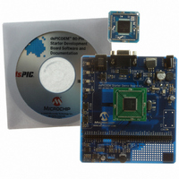
BOARD DEMO DSPICDEM 80L STARTER
Manufacturer
Microchip Technology
Type
MCUr
Specifications of DM300019
Contents
Board, CD, Sample Part
Processor To Be Evaluated
dsPIC30F and dsPIC33F
Interface Type
RS-232
Silicon Manufacturer
Microchip
Silicon Core Number
DsPIC30F6014A, DsPIC33FJ256GP710
Silicon Family Name
DsPIC30F And DsPIC33F
Kit Contents
Development Board And Docs On CD
Rohs Compliant
Yes
Lead Free Status / RoHS Status
Lead free / RoHS Compliant
For Use With/related Products
dsPIC30F, dsPIC33F
Lead Free Status / Rohs Status
Lead free / RoHS Compliant
Available stocks
Company
Part Number
Manufacturer
Quantity
Price
Company:

Part Number:
DM300019
Manufacturer:
Microchip Technology
Quantity:
135
Company:
Part Number:
DM300019
Manufacturer:
MICROCHIP
Quantity:
12 000


dsPICDEM™ 80-Pin Starter Development Board User’s Guide
DS51584B-page 34
4.1.1
One RS-232 serial communication channel is provided on the board. This channel is
labeled J1. The dsPIC DSC or PIC24 MCU UART channel 1 U1RX and U1TX pins are
connected to an RS-232 level shifting MAX3232CD (U3), as shown in Figure A-3. The
serial port is configured as DCE and can be connected to a PC using a straight through
cable.
4.1.2
An analog potentiometer (R13) is connected to analog channel AN2 on the dsPIC DSC
or PIC24 MCU device. The voltage output range for the potentiometer is 0-5 VDC. The
voltage source is provided by the +5VAN regulator, as shown in Figure A-6.
4.1.3
Two push button switches (S1 and S2) are connected to port pin RA12 and RA13,
respectively, on the dsPIC DSC or PIC24 MCU device, as shown in Figure A-3. The
signal lines are normally pulled up to V
shorts the line to ground. Port pins RA12 and RA13 are configured as input pins.
4.1.4
Four LED indicators (D2 to D5) are connected to port pins RD4 to RD7, respectively,
on the dsPIC DSC or PIC24 MCU device. The anode of each LED is tied to V
through a 470 ohm resistor, as shown in Figure A-3. The cathodes are shorted and
connected to GND by an activation header (J4). The LEDs are labeled RD4 through
RD7 on the board to correspond to their respective port pins.
4.1.5
A single channel digital potentiometer (U2) is provided on the development board. The
MCP41010_SO150 digital potentiometer is controlled by the SPI2 communication
channel on the dsPIC DSC or PIC24 MCU device. The output of the digital
potentiometer is applied to a 2nd-order, low-pass filter, with a cutoff frequency of
approximately 4 kHz. The output of the LP filter is connected to the LINE OUT pin of
J9, as shown in Figure A-6.
4.1.6
A Microchip MCP6022_SO8 Operational Amplifier is configured as a 2nd-order,
low-pass filter for speech or voice input filtering, as shown in Figure A-6. The input to
the filter is at the LINE IN pin of J9.
4.1.7
By way of the modular connector ICD (J3), the MPLAB ICD 2 can be connected for
low-cost programming and debugging of the dsPIC DSC or PIC24 MCU device.
4.1.8
Header P1 supports the processor adaptor boards. The processor adaptor boards
enable quick change out of the device.
4.1.9
Header P2 is a two-row header with appropriate labels for I/O ports. This header allows
the user to easily probe appropriate I/O lines.
RS-232 Serial Port
Analog Potentiometer
Push Button Switches
LED Indicators
Digital Potentiometer
Low-Pass Filter
ICD 2 Connector
Device Header
I/O Port Header
DD
through 4.7K resistors. Pressing the switch
© 2006 Microchip Technology Inc.
DD
Related parts for DM300019
Image
Part Number
Description
Manufacturer
Datasheet
Request
R

Part Number:
Description:
Manufacturer:
Microchip Technology Inc.
Datasheet:
Part Number:
Description:
Manufacturer:
Microchip Technology Inc.
Datasheet:
Part Number:
Description:
Manufacturer:
Microchip Technology Inc.
Datasheet:
Part Number:
Description:
Manufacturer:
Microchip Technology Inc.
Datasheet:
Part Number:
Description:
Manufacturer:
Microchip Technology Inc.
Datasheet:
Part Number:
Description:
Manufacturer:
Microchip Technology Inc.
Datasheet:
Part Number:
Description:
Manufacturer:
Microchip Technology Inc.
Datasheet:
Part Number:
Description:
Manufacturer:
Microchip Technology Inc.
Datasheet: