DM183032 Microchip Technology, DM183032 Datasheet - Page 27
DM183032
Manufacturer Part Number
DM183032
Description
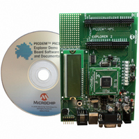
BOARD EXPLORER PICDEM PIC18
Manufacturer
Microchip Technology
Series
MPLAB®r
Type
MCUr
Datasheet
1.DM183032.pdf
(38 pages)
Specifications of DM183032
Contents
Evaluation Board
Processor To Be Evaluated
PIC 18
Data Bus Width
8 bit
Interface Type
RS-232, USB
Silicon Manufacturer
Microchip
Core Architecture
PIC
Core Sub-architecture
PIC18
Silicon Core Number
PIC18F
Silicon Family Name
PIC18F8xxx, PIC18FxxJxx
Lead Free Status / RoHS Status
Lead free / RoHS Compliant
For Use With/related Products
PIC18 Series
Lead Free Status / Rohs Status
Lead free / RoHS Compliant
Available stocks
Company
Part Number
Manufacturer
Quantity
Price
Company:

Part Number:
DM183032
Manufacturer:
Microchip Technology
Quantity:
135
Company:
Part Number:
DM183032
Manufacturer:
MICROCHIP
Quantity:
12 000


3.1
© 2008 Microchip Technology Inc.
Chapter 3. PICDEM™ PIC18 Explorer Demonstration
TUTORIAL PROGRAM OPERATION
The tutorial program is preprogrammed into the PIC18F8722 on the PICDEM PIC18
Explorer Demonstration Board. This program is also on the PICDEM PIC18 Explorer
Demonstration Board kit’s CD-ROM so that it can be reprogrammed on the sample
device if it the device had been preprogrammed.
For detailed information on the PICDEM PIC18 Explorer Demonstration Board
hardware, see Appendix A. “Hardware Details”.
The tutorial program consists of three components that appear sequentially on the
board’s LCD. A flowchart, showing the button navigation through the entire program, is
given in Figure 3-2.
When the board boots up, the device name appears on the LCD and the program
proceeds to the first component.
To select menu options, use the RB0 and RA5 buttons on the bottom of the board (see
Figure 3-1).
FIGURE 3-1:
1. Voltmeter
This mode uses the Analog-to-Digital Converter (A/D) module to measure the voltage
of the R3 potentiometer and display a value between 0.00V and 5.00V on the LCD. (In
the case of 3.3V devices, the displayed value will be 0.00V to 3.3V.)
The voltage reading is updated continually until the mode is exited by pressing RB0.
2. Temperature
This mode uses an MCP9701A thermal sensor to measure ambient temperature in
Celsius and displays it on the LCD. The program also stores the current temperature,
when exited, by writing to a defined address on the external, on-board EEPROM.
Communication between the microcontroller and sensor is done by the A/D module.
To exit this mode, press RB0.
RB0 Button
RA5 Button
Board Tutorial Program
RB0 AND RA5 BUTTONS
PICDEM™ PIC18 EXPLORER
DEMONSTRATION BOARD
USER’S GUIDE
DS51721B-page 23
Related parts for DM183032
Image
Part Number
Description
Manufacturer
Datasheet
Request
R

Part Number:
Description:
Manufacturer:
Microchip Technology Inc.
Datasheet:
Part Number:
Description:
Manufacturer:
Microchip Technology Inc.
Datasheet:
Part Number:
Description:
Manufacturer:
Microchip Technology Inc.
Datasheet:
Part Number:
Description:
Manufacturer:
Microchip Technology Inc.
Datasheet:
Part Number:
Description:
Manufacturer:
Microchip Technology Inc.
Datasheet:
Part Number:
Description:
Manufacturer:
Microchip Technology Inc.
Datasheet:
Part Number:
Description:
Manufacturer:
Microchip Technology Inc.
Datasheet:
Part Number:
Description:
Manufacturer:
Microchip Technology Inc.
Datasheet: