DM240001 Microchip Technology, DM240001 Datasheet - Page 27
DM240001
Manufacturer Part Number
DM240001
Description
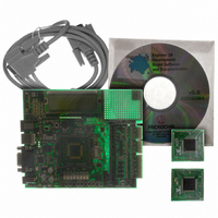
BOARD DEMO PIC24/DSPIC33/PIC32
Manufacturer
Microchip Technology
Series
Explorer 16 100-pinr
Type
MCUr
Specifications of DM240001
Contents
Explorer 16 Dev Board, PIC24FJ128GA010 and dsPIC33FJ256GP710 PIM Modules
Processor To Be Evaluated
PIC 24 and dsPIC33
Data Bus Width
16 bit
Interface Type
RS-232
Silicon Manufacturer
Microchip
Core Architecture
PIC, DsPIC
Core Sub-architecture
PIC24, DsPIC33
Silicon Core Number
PIC24F, DsPIC33F
Rohs Compliant
Yes
Lead Free Status / RoHS Status
Lead free / RoHS Compliant
For Use With/related Products
dsPIC30, dsPIC33, PIC32, PIC24FJ, PIC24HJ
For Use With
AC164127-5 - BOARD GRAPH LCD CNTLR PICTAILAC164127-3 - BOARD DAUGHTER GRAPHIC PICTAILAC164127 - BRD DAUGHT GRAPHIC PICTAIL PLUS
Lead Free Status / Rohs Status
Lead free / RoHS Compliant
Available stocks
Company
Part Number
Manufacturer
Quantity
Price
Company:

Part Number:
DM240001
Manufacturer:
MICROCHIP
Quantity:
12 000


3.1
3.2
© 2005 Microchip Technology Inc.
INTRODUCTION
PIC24 TUTORIAL PROGRAM OPERATION
Chapter 3. Explorer 16 Tutorial Programs
This chapter provides a high-level overview of the PIC24 and dsPIC33F firmware
programmed during the tutorial exercise in the previous chapter.
The PIC24 tutorial program is made up of three components which are individually
displayed on the LCD. The program is used to demonstrate the new Parallel Master
Port (PMP) module which is used to drive the LCD, as well as the new Real-Time
Clock/Calendar module (RTCC). The program flow is shown in Figure 3-1.
3.2.1
Features mode displays a continuous description of the PIC24FJ128GA010 device
feature set. To exit the display and continue to the next mode, press S4.
3.2.2
Voltmeter/Temperature mode uses the code modules, vbanner.c and ADC.c, and
the A/D module to measure analog signals from the board and convert them for display
on the LCD. The voltage is taken from the potentiometer (R6) and displays a voltage
between 0.00V and 3.29V on line 1 of the LCD. Temperature is from a TC1074A analog
thermal sensor (U5). The temperature is displayed on line 2 of the LCD and auto-
matically alternates between Celsius and Fahrenheit values. The voltage and
temperature are updated continuously.
This mode also lets users store the current temperature in the on-board serial
EEPROM by pressing S5. Pressing S6 switches the display between current and
stored temperature values. An ‘M’ on the right side of the LCD indicates that a stored
temperature value is being displayed.
To exit and continue to the next mode, press S4.
3.2.3
Clock/Calendar mode uses code in the modules, rtcc.c and tbanner.c. Once this
mode is entered from the main menu, a Real-Time Clock will start counting from
10:00:00, and display the date and day for Oct. 10, 2005. The new RTCC module and
a 32 kHz clock crystal are used to provide the Real-Time Clock with day/date calendar.
In Clock/Calendar mode, the user-defined push buttons do the following:
• S3 toggles the Clock Set mode, which allows the user to set the date and time.
• S4 accepts the value of the current item and moves cursor to the next item.
• S5 decrements the currently selected item.
• S6 increments the currently selected item.
Pressing S3 once superimposes a flashing cursor over the tens digit of the hour in the
time display. Each press of S4 moves the cursor sequentially through the digits of the
time display, then the month, day and year. Pressing S3 at any time in the process
returns to the regular clock/calendar display.
Setup mode starts with the tens digit of the hour in the time display.
PIC24 Features
Voltmeter/Temperature
Clock/Calendar
EXPLORER 16 DEVELOPMENT
BOARD USER’S GUIDE
DS51589A-page 23
Related parts for DM240001
Image
Part Number
Description
Manufacturer
Datasheet
Request
R

Part Number:
Description:
Manufacturer:
Microchip Technology Inc.
Datasheet:
Part Number:
Description:
Manufacturer:
Microchip Technology Inc.
Datasheet:
Part Number:
Description:
Manufacturer:
Microchip Technology Inc.
Datasheet:
Part Number:
Description:
Manufacturer:
Microchip Technology Inc.
Datasheet:
Part Number:
Description:
Manufacturer:
Microchip Technology Inc.
Datasheet:
Part Number:
Description:
Manufacturer:
Microchip Technology Inc.
Datasheet:
Part Number:
Description:
Manufacturer:
Microchip Technology Inc.
Datasheet:
Part Number:
Description:
Manufacturer:
Microchip Technology Inc.
Datasheet: