DM240001 Microchip Technology, DM240001 Datasheet - Page 31
DM240001
Manufacturer Part Number
DM240001
Description
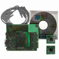
BOARD DEMO PIC24/DSPIC33/PIC32
Manufacturer
Microchip Technology
Series
Explorer 16 100-pinr
Type
MCUr
Specifications of DM240001
Contents
Explorer 16 Dev Board, PIC24FJ128GA010 and dsPIC33FJ256GP710 PIM Modules
Processor To Be Evaluated
PIC 24 and dsPIC33
Data Bus Width
16 bit
Interface Type
RS-232
Silicon Manufacturer
Microchip
Core Architecture
PIC, DsPIC
Core Sub-architecture
PIC24, DsPIC33
Silicon Core Number
PIC24F, DsPIC33F
Rohs Compliant
Yes
Lead Free Status / RoHS Status
Lead free / RoHS Compliant
For Use With/related Products
dsPIC30, dsPIC33, PIC32, PIC24FJ, PIC24HJ
For Use With
AC164127-5 - BOARD GRAPH LCD CNTLR PICTAILAC164127-3 - BOARD DAUGHTER GRAPHIC PICTAILAC164127 - BRD DAUGHT GRAPHIC PICTAIL PLUS
Lead Free Status / Rohs Status
Lead free / RoHS Compliant
Available stocks
Company
Part Number
Manufacturer
Quantity
Price
Company:

Part Number:
DM240001
Manufacturer:
MICROCHIP
Quantity:
12 000


4.1
4.2
© 2005 Microchip Technology Inc.
HARDWARE FEATURES
INTRODUCTION
Chapter 4. Explorer 16 Development Hardware
This chapter provides a more detailed description of the hardware features of the
Explorer 16 Development Board.
The key features of the Explorer 16 board are listed below. They are presented in the order
given in Section 1.4 “Explorer 16 Development Board Functionality and Features”,
Figure 1-1.
4.2.1
The Explorer 16 board has been designed to accommodate both permanently mounted
(i.e., soldered on) and detachable PIM processors. Slider switch, S2, allows the user
to choose which processor to use. This makes it possible for the Explorer 16 board to
support most 3V, 16-bit, pin compatible microcontrollers with appropriate PIMs.
PIMs are visually indexed for proper installation. The PIM is always installed with the
notched corner mark on the corner of the PIM board oriented to the upper left corner.
Current revisions of the board do not have a permanently mounted microcontroller in
U1. In order for the board to work, therefore, S2 must always be left in the “PIM” posi-
tion. In future versions with a permanently mounted PIC24 device at U1, setting S2 in
the “PIC” position will enable the on-board device and disable the PIM socket.
4.2.2
There are two ways to supply power to the Explorer 16 board:
• An unregulated DC supply of 9V to 15V (preferably 9V) supplied to J12.
• An external, regulated DC power supply that provides both +5V and +3.3V can be
One green LED (D1) is provided to show when the Explorer 16 board is powered up.
The power-on LED indicates the presence of +3.3V.
For default functionality, a power supply with a current capability of 250 mA is
sufficient. Since the board can serve as a modular development platform that can
connect to multiple expansion boards, voltage regulators (Q1 and Q2) with a
maximum current capability of 800 mA are used. This may require a larger power
supply of up to 1.6A. Because the regulators do not have heat sinks, long-term
operation at such loads is not recommended.
connected to the terminals provided (at the bottom left side of the board, near S3).
Note:
Note:
Processor Support
Power Supply
The Explorer 16 kit does not include a power supply. If an external supply
is needed, use Microchip part number AC162039.
Do not attempt to power the Explorer 16 board using the MPLAB ICD 2
module. It is not designed to be a USB bus power source.
EXPLORER 16 DEVELOPMENT
BOARD USER’S GUIDE
DS51589A-page 27
Related parts for DM240001
Image
Part Number
Description
Manufacturer
Datasheet
Request
R

Part Number:
Description:
Manufacturer:
Microchip Technology Inc.
Datasheet:
Part Number:
Description:
Manufacturer:
Microchip Technology Inc.
Datasheet:
Part Number:
Description:
Manufacturer:
Microchip Technology Inc.
Datasheet:
Part Number:
Description:
Manufacturer:
Microchip Technology Inc.
Datasheet:
Part Number:
Description:
Manufacturer:
Microchip Technology Inc.
Datasheet:
Part Number:
Description:
Manufacturer:
Microchip Technology Inc.
Datasheet:
Part Number:
Description:
Manufacturer:
Microchip Technology Inc.
Datasheet:
Part Number:
Description:
Manufacturer:
Microchip Technology Inc.
Datasheet: