ATEVK1104 Atmel, ATEVK1104 Datasheet
ATEVK1104
Specifications of ATEVK1104
Available stocks


Related parts for ATEVK1104


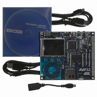
ATEVK1104 Summary of contents
Page 1
AVR32787: AVR32 AT32UC3A3 High Speed USB Design Guidelines 1. Introduction This document provides guidelines for integrating an AVR speed USB device controller onto a 4-layer PCB. The material covered can be broken into two main categories: board design guidelines and ...
Page 2
Layout Guidelines 2.1 General Routing and Placement Use the following general routing and placement guidelines when laying out a new design. These guidelines will help to minimize signal quality problems. 1. Place the high-speed USB host controller and major ...
Page 3
Figure 2-1. Low speed/ non periodic signal Table 2-1. 2.3 High Speed USB Termination The AVR32 AT32UC3A3x microcontroller high-speed USB design requires 39 Ω termination resistor at both DMFS and DPFS pins. Place the termination resistors as close as possible ...
Page 4
High Speed USB Connectors In order to provide direct connection of high-speed USB signals, we recommend to use through hole mini-AB or surface mount mini-AB receptacle connector. In case AT32UC3A3x OTG capa- bility is not requested, we recommend to ...
Page 5
Figure 3-2. Note: 32122B–AVR32–04/09 Standard Mini AB Receptacle - USB Routing Example with BGA144 Package Ground plane For R1, R2, R3, C1 values, refer to AT32UC3A3x datasheet. Mini AB J1 GND VBUS ...
Page 6
... Disclaimer: The information in this document is provided in connection with Atmel products. No license, express or implied, by estoppel or otherwise, to any intellectual property right is granted by this document or in connection with the sale of Atmel products. EXCEPT AS SET FORTH IN ATMEL’S TERMS AND CONDI- TIONS OF SALE LOCATED ON ATMEL’S WEB SITE, ATMEL ASSUMES NO LIABILITY WHATSOEVER AND DISCLAIMS ANY EXPRESS, IMPLIED OR STATUTORY WARRANTY RELATING TO ITS PRODUCTS INCLUDING, BUT NOT LIMITED TO, THE IMPLIED WARRANTY OF MERCHANTABILITY, FITNESS FOR A PARTICULAR PURPOSE, OR NON-INFRINGEMENT ...