AT91SAM7SE-EK Atmel, AT91SAM7SE-EK Datasheet - Page 32
AT91SAM7SE-EK
Manufacturer Part Number
AT91SAM7SE-EK
Description
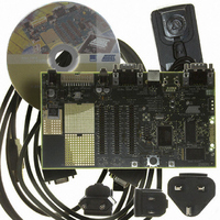
EVAL BOARD FOR AT91SAM7SE
Manufacturer
Atmel
Series
AT91SAM Smart ARMr
Type
MCUr
Datasheet
1.AT91SAM7SE-EK.pdf
(36 pages)
Specifications of AT91SAM7SE-EK
Contents
Evaluation Board, Parallel Cable and CD-ROM
Processor To Be Evaluated
AT91SAM7SE
Data Bus Width
32 bit
Interface Type
RS-232, USB
Silicon Manufacturer
Atmel
Core Architecture
ARM
Core Sub-architecture
ARM7TDMI
Silicon Core Number
AT91SAM7SE
Silicon Family Name
ARM
Kit Contents
Board CD Docs
Rohs Compliant
Yes
For Use With/related Products
AT91SAM7SE
Lead Free Status / RoHS Status
Lead free / RoHS Compliant


6.1
6.2
6.3
AT91SAM7SE-EK Evaluation Board User Guide
PIO Usage
TWI line pullups
for Fast Mode
operation
AT73C213
clocking
The PIO PC19 is erroneously used twice.
USB_CNX (VBUS detect) and A21/ALE (NAND Flash Address Latch Enable) uses this
PIO. There is no effect when PC19 is configured as A21 for the NAND Flash usage, but
USB_CNX state (VBUS) cannot be read at the same time.
The user has to swap PC19 to input mode to detect the VBUS state, but the NANDFlash
cannot be accessed in this configuration.
In order to use the TWI in Fast Mode (up to 400 Kbits/s), the default 10 K resistors R28
and R29 should be replaced by smaller values (e.g., 2.2 K ).
Note that there is no need to change the pull-up resistors if the TWI is used in Standard
Mode (up to 100 Kbits/s).
In the schematics (sheet 1/7, ”AT91SAM7SE-EK Diagram”), the MCLK and BCLK
sources implementation does not guarantee a correct phase relation as specified in the
AT73C213 datasheet.
Problem Fix/Workaround
In his own design, the user must make sure the BCLK and MCLK clocks generation
implements the timing specified in the AT73C213 datasheet.
Section 6
6241B–ATARM–22-Mar-07
Errata
6-1
Related parts for AT91SAM7SE-EK
Image
Part Number
Description
Manufacturer
Datasheet
Request
R

Part Number:
Description:
MCU ARM9 64K SRAM 144-LFBGA
Manufacturer:
Atmel
Datasheet:

Part Number:
Description:
IC ARM7 MCU FLASH 256K 100LQFP
Manufacturer:
Atmel
Datasheet:

Part Number:
Description:
IC ARM9 MPU 217-LFBGA
Manufacturer:
Atmel
Datasheet:
Part Number:
Description:
MCU ARM9 ULTRA LOW PWR 217-LFBGA
Manufacturer:
Atmel
Datasheet:

Part Number:
Description:
MCU ARM9 324-TFBGA
Manufacturer:
Atmel
Datasheet:
Part Number:
Description:
IC MCU ARM9 SAMPLING 217CBGA
Manufacturer:
Atmel
Datasheet:
Part Number:
Description:
IC ARM9 MCU 217-LFBGA
Manufacturer:
Atmel
Datasheet:

Part Number:
Description:
IC ARM9 MCU 208-PQFP
Manufacturer:
Atmel
Datasheet:
Part Number:
Description:
MCU ARM 512K HS FLASH 100-LQFP
Manufacturer:
Atmel
Datasheet:

Part Number:
Description:
MCU ARM 512K HS FLASH 100-TFBGA
Manufacturer:
Atmel
Datasheet:
Part Number:
Description:
IC ARM9 MCU 200 MHZ 324-TFBGA
Manufacturer:
Atmel
Datasheet:

Part Number:
Description:
IC ARM MCU 16BIT 128K 256BGA
Manufacturer:
Atmel
Datasheet:

Part Number:
Description:
IC ARM7 MCU 32BIT 128K 64LQFP
Manufacturer:
Atmel
Datasheet:

Part Number:
Description:
IC ARM7 MCU FLASH 256K 128-LQFP
Manufacturer:
Atmel
Datasheet:
Part Number:
Description:
IC ARM7 MCU FLASH 512K 128-LQFP
Manufacturer:
Atmel
Datasheet: