AT91SAM9XE-EK Atmel, AT91SAM9XE-EK Datasheet
AT91SAM9XE-EK
Specifications of AT91SAM9XE-EK
Available stocks


Related parts for AT91SAM9XE-EK


AT91SAM9XE-EK Summary of contents
Page 1
... AT91SAM9XE-EK Evaluation Board .................................................................................................................... User Guide 6311A–ATARM–04-Feb-08 ...
Page 2
... Table of Contents Section 1 Overview .................................................................................................................... 1-1 1.1 Scope................................................................................................................................. 1-1 1.2 Deliverables ....................................................................................................................... 1-1 1.3 AT91SAM9XE-EK Evaluation Board ................................................................................. 1-1 Section 2 Setting Up the AT91SAM9XE-EK Board.................................................................... 2-1 2.1 Electrostatic Warning ......................................................................................................... 2-1 2.2 Requirements..................................................................................................................... 2-1 2.3 Layout ................................................................................................................................ 2-1 2.4 Powering Up the Board...................................................................................................... 2-4 2.5 Backup Power Supply........................................................................................................ 2-4 2 ...
Page 3
... Table of Contents (Continued) 4.3 Microcontroller Clock ......................................................................................................... 4-2 4.4 Memory Configuration........................................................................................................ 4-2 4.5 Ethernet ............................................................................................................................. 4-3 4.6 Miscellaneous .................................................................................................................... 4-3 Section 5 Schematics................................................................................................................. 5-1 5.1 Schematics ........................................................................................................................ 5-1 Section 6 Revision History ......................................................................................................... 6-1 6.1 Revision History ................................................................................................................. 6-1 ii 6311A–ATARM–04-Feb-08 AT91SAM9XE-EK Evaluation Board User Guide ...
Page 4
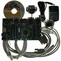
... Scope The AT91SAM9XE-EK evaluation kit enables the evaluation of and code development for applications running on an AT91SAM9XE device. This guide focuses on the AT91SAM9XE-EK board as an evaluation platform. The board supports the AT91SAM9XE in an LFBGA217 package as well PQFP208 package. 1.2 Deliverables The AT91SAM9XE-EK package contains the following items: ...
Page 5
... DataFlash, SD/MMC card slot four expansion connectors (PIOA, PIOB, PIOC, IMAGE SENSOR) one BGA-like EBI expansion footprint connector one Lithium Coin Cell Battery Retainer for 12 mm cell size 1-2 6311A–ATARM–04-Feb-08 AT91SAM9XE-EK Evaluation Board User Guide ...
Page 6
... A grounding strap or similar protective device should be worn when handling the board. Avoid touching the component pins or any other metallic element. 2.2 Requirements In order to set up the AT91SAM9XE-EK evaluation board, the following items are needed: the AT91SAM9XE-EK evaluation board itself. AC/DC power adapter (5V at 2A), 2 5.5 mm 2.3 ...
Page 7
... Figure 2-1. AT91SAM9XE-EK Layout-Top View 2-2 6311A–ATARM–04-Feb-08 AT91SAM9XE-EK Evaluation Board User Guide ...
Page 8
... Figure 2-2. AT91SAM9XE-EK Layout - Bottom View AT91SAM9XE-EK Evaluation Board User Guide 2-3 6311A–ATARM–04-Feb-08 ...
Page 9
... Powering Up the Board The AT91SAM9XE-EK requires 5V DC (±5%). DC power is supplied to the board via the 2 5.5 mm socket J1. Coaxial plug center positive standard. 2.5 Backup Power Supply The user has the possibility to plug a battery (3V Lithium Battery CR1225 or equivalent) in order to per- manently power the backup part of the device. In this case, J10 configuration must be set in position 1, 2. ...
Page 10
... AT91SAM9XE-EK Block Diagram Figure 2-3. AT91SAM9XE-EK Block Diagram AT91SAM9XE-EK Evaluation Board User Guide 2-5 6311A–ATARM–04-Feb-08 ...
Page 11
... Data Interface for Support of High Sensibility Sensors – SAV and EAV Synchronization, Preview Path with Scaler, YCbCr Format • Bus Matrix – Six 32-bit-layer Matrix – Remap Command AT91SAM9XE-EK Evaluation Board User Guide ® ® Thumb Processor ® ® ...
Page 12
... Two Three-channel 16-bit Timer/Counters (TC) – Three External Clock Inputs, Two Multi-purpose I/O Pins per Channel – Double PWM Generation, Capture/Waveform Mode, Up/Down Capability – High-Drive Capability on Outputs TIOA0, TIOA1, TIOA2 3-2 6311A–ATARM–04-Feb-08 ™ Compliant ® Infrared Modulation/Demodulation AT91SAM9XE-EK Evaluation Board User Guide ...
Page 13
... VDDIOP1 (Peripheral I/Os) – 3.0V to 3.6V for VDDIOP0 and VDDANA (Analog-to-digital Converter) – Programmable 1.65V to 1.95V or 3.0V to 3.6V for VDDIOM (Memory I/Os) • Available in a 208-pin PQFP Green and a 217-ball LFBGA Green Package AT91SAM9XE-EK Evaluation Board User Guide 3-3 6311A–ATARM–04-Feb-08 ...
Page 14
... Block Diagram Figure 3-1. AT91SAM9XE512/256/128 Block Diagram 3-4 6311A–ATARM–04-Feb-08 Filter AT91SAM9XE-EK Evaluation Board User Guide ...
Page 15
... One serial interface (DBGU COM Port) via RS-232 DB9 male socket One complete modem serial interface (COM Port 0) via RS-232 DB9 male socket One additional serial interface (COM Port 1) with RTS/CTS handshake control via RS-232 DB9 male AT91SAM9XE-EK Evaluation Board User Guide 3-5 6311A–ATARM–04-Feb-08 ...
Page 16
... This allows the developer to check the integrity of the components and to extend the features of the board by adding external hardware components or boards. Notes: 1. Only one available with the 208-lead PQFP package. 2. Not available with the 208-lead PQFP package. 3-6 6311A–ATARM–04-Feb-08 (2) AT91SAM9XE-EK Evaluation Board User Guide ...
Page 17
... PA23 TWD PA24 TWCK PA25 TCLK0 PA26 TIOA0 PA27 TIOA1 PA28 TIOA2 PA29 SCK1 PA30 SCK2 PA31 SCK0 AT91SAM9XE-EK Evaluation Board User Guide Peripheral B Comments MCDB0 MCCDB MCDB3 MCDB2 MCDB1 ETX2 ETX3 ETXER ETX2 ETX3 ERX2 ERX3 High-Drive ERXCK High-Drive ECRS ...
Page 18
... Audio DAC AT73C213 (BCLK) Audio DAC AT73C213 (LRFS) Audio DAC AT73C213 (SDIN) (J28) IMAGE SENSOR CONNECTOR (CTRL2) (J28) IMAGE SENSOR CONNECTOR (PB20..PB31) Warning: Shared with COM PORT 0 (PB22..PB27) Warning: Shared with COM PORT 1 (PB28..PB29) AT91SAM9XE-EK Evaluation Board User Guide ...
Page 19
... PC23 D23 PC24 D24 PC25 D25 PC26 D26 PC27 D27 PC28 D28 PC29 D29 PC30 D30 PC31 D31 AT91SAM9XE-EK Evaluation Board User Guide Peripheral B Comments SCK3 PCK0 PCK1 SPI1_NPCS3 SPI1_NPCS2 SPI1_NPCS1 CFCE1 CFCE2 RTS3 TIOB0 CTS3 SPI0_NPCS1 NCS7 NCS6 IRQ2 IRQ1 ...
Page 20
... J7 J9 J10 J12 J15 J32 J33 Notes: 1. These jumpers are provided for power consumption measurement. By default, they are AT91SAM9XE-EK Evaluation Board User Guide Default Setting Feature Closed 3.3V Jumper Forces power on. Closed To use the software shutdown control, J3 must be opened. 3V battery backup must be present. ...
Page 21
... Enables MN7 Chip select access Soldered Enables MN8 Chip select access Soldered Enables the use of Ready Busy signal Opened Opened Soldered Soldered AT91SAM9XE-EK Evaluation Board User Guide Feature unsoldered. Enables the ICE NRST input Feature Table 4-1 . Feature Disables write protection. ...
Page 22
... R86 R88 TP1 TP2 TP3 TP4 TP5 TP6 AT91SAM9XE-EK Evaluation Board User Guide Default Setting Soldered USB DEVICE: Enables the use of the USBCNX signal Soldered DBGU COM Port: Enables the use of DTXD output signal. Enables the use of DRXD input. Soldered RS232 COM Port 0: Enable the use of output signals. ...
Page 23
... This section contains the following schematics: Board Diagram - Schematic Top Level Power supply and audio 217-ball BGA AT91SAM9XE Microcontroller 208-pin LQFP AT91SAM9XE Microcontroller Memory Ethernet Serial Interface Expansion and User Interface AT91SAM9XE-EK Evaluation Board User Guide Section 5 Schematics 5-1 6311A–ATARM–04-Feb-08 ...
Page 24
...
Page 25
...
Page 26
...
Page 27
...
Page 28
...
Page 29
...
Page 30
...
Page 31
...
Page 32
... Revision History Table 6-1. Document 6311A AT91SAM9XE-EK Evaluation Board User Guide Comments First issue. Section 6 Revision History Change Request Ref. 6-1 6311A–ATARM–04-Feb-08 ...
Page 33
... AT91SAM9XE-EK Evaluation Board User Guide ...
Page 34
... Disclaimer: The information in this document is provided in connection with Atmel products. No license, express or implied, by estoppel or otherwise, to any intellectual property right is granted by this document or in connection with the sale of Atmel products. EXCEPT AS SET FORTH IN ATMEL’S TERMS AND CONDI- TIONS OF SALE LOCATED ON ATMEL’S WEB SITE, ATMEL ASSUMES NO LIABILITY WHATSOEVER AND DISCLAIMS ANY EXPRESS, IMPLIED OR STATUTORY WARRANTY RELATING TO ITS PRODUCTS INCLUDING, BUT NOT LIMITED TO, THE IMPLIED WARRANTY OF MERCHANTABILITY, FITNESS FOR A PARTICULAR PURPOSE, OR NON-INFRINGEMENT ...