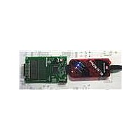
DM164130-1 Microchip Technology, DM164130-1 Datasheet - Page 15

DM164130-1
Manufacturer Part Number
DM164130-1
Description
BOARD EVAL PICKIT PIC16LF1937
Manufacturer
Microchip Technology
Series
PICkit™r
Type
MCUr
Datasheet
1.DM164130-1.pdf
(42 pages)
Specifications of DM164130-1
Contents
Board
Processor To Be Evaluated
PIC16LF1937
Processor Series
PICxxF1xxx
Data Bus Width
8 bit
Operating Supply Voltage
1.8 V to 3.6 V
Silicon Manufacturer
Microchip
Core Architecture
PIC
Core Sub-architecture
PIC16
Silicon Core Number
PIC16F
Silicon Family Name
PIC12F1xxx, PIC16F1xxx
Lead Free Status / RoHS Status
Lead free / RoHS Compliant
For Use With/related Products
PIC16LF1937
Lead Free Status / Rohs Status
Lead free / RoHS Compliant
Available stocks
Company
Part Number
Manufacturer
Quantity
Price
Company:
Part Number:
DM164130-1
Manufacturer:
Microchip Technology
Quantity:
135
Company:
Part Number:
DM164130-10
Manufacturer:
MICROCHIP
Quantity:
12 000
2.6
2.7
© 2009 Microchip Technology Inc.
POWERING WITH THE BLDC EXPANSION HEADER J3
DEFAULT FIRMWARE
The BLDC Expansion hardware contains a 3.3V linear regulator. This allows the 5-12V
motor power supply to power the PIC16LF1937. J3 pin 6 is the source for the 3.3V
power. To use this power perform the following steps.
1. Make sure a jumper or an ammeter is connected across JP2.
2. Insert the shorting jumper at JP1.
3. Verify that any attached PICkit 3 or PICkit serial is not supplying power.
4. Verify that there is NO power supply or shorting jumper at JP3.
5. Verify that the BLDC expansion hardware provides less than 3.6V of power. (The
6. Attach the BLDC expansion board.
7. Supply power via the BLDC board.
The default firmware supplied with your F1 Evaluation Board Demo has the following
features:
1. Blink LEDs
2. Measure the ambient temperature
3. Run a BLDC motor (or try to if no motor is attached)
4. Display time/temperature/pot position/motor RPM on the LCD
5. User interface with a button and pot
For the latest firmware go to www.microchip.com/F1Eval
2.7.1
The 4 LEDs indicate motor phase operation (D<2:4>) and the performance of the
primary state machine loop (D1).
2.7.2
The MCP9800 is polled when in Temperature Measurement mode. The measured
temperature is filtered, scaled to centigrade and displayed on the LCD.
2.7.3
One task of the demo code is to drive a BLDC motor attached to the BLDC Expansion
Header. The optional BLDC Controller board (DM164130-2) is required to drive the
motor. The code performs a series of forced commutation steps to attempt a sensorless
motor start. If no back EMF signal is detected, the code repeats the start-up sequence.
The LEDs blink at an increasing rate indicating the motor start attempts. If no motor
drive hardware is attached, this pattern can repeat or it may detect a BEMF signal in
the noise present on the BEMF sense inputs.
F1 BLDC add-on supplies 3.3V)
Blinking LEDs
Measuring the Ambient Temperature
BLDC Motor
Getting Started
DS41401A-page 15


