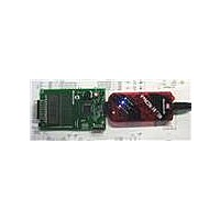
DM164130-1 Microchip Technology, DM164130-1 Datasheet - Page 16

DM164130-1
Manufacturer Part Number
DM164130-1
Description
BOARD EVAL PICKIT PIC16LF1937
Manufacturer
Microchip Technology
Series
PICkit™r
Type
MCUr
Datasheet
1.DM164130-1.pdf
(42 pages)
Specifications of DM164130-1
Contents
Board
Processor To Be Evaluated
PIC16LF1937
Processor Series
PICxxF1xxx
Data Bus Width
8 bit
Operating Supply Voltage
1.8 V to 3.6 V
Silicon Manufacturer
Microchip
Core Architecture
PIC
Core Sub-architecture
PIC16
Silicon Core Number
PIC16F
Silicon Family Name
PIC12F1xxx, PIC16F1xxx
Lead Free Status / RoHS Status
Lead free / RoHS Compliant
For Use With/related Products
PIC16LF1937
Lead Free Status / Rohs Status
Lead free / RoHS Compliant
Available stocks
Company
Part Number
Manufacturer
Quantity
Price
Company:
Part Number:
DM164130-1
Manufacturer:
Microchip Technology
Quantity:
135
Company:
Part Number:
DM164130-10
Manufacturer:
MICROCHIP
Quantity:
12 000
F1 Evaluation Platform User’s Guide
DS41401A-page 16
2.7.4
The time, temperature, pot position and motor speed are displayed on the LCD. The
LCD is a 3.5-digit multimeter display with icons for amps, volts, ohms, etc. The display
uses 4 commons and 10 segment drives. The Timer1 oscillator is used to clock the
display peripheral and allow the display to show a picture even in Sleep. The LCD
peripheral was configured for a Type B waveform for this demo. This mode provides an
interrupt when the LCD can be updated. This interrupt is not required for Type A
waveforms, but the extra complexity of the interrupt allows the LCD peripheral to be
used to provide the real-time clock periodic interrupt. The different waveform types are
described in section 21.9 of the PIC16LF193X data sheet (DS41364). Normally, the
Timer1 counter would be used, but this timer is required for the BLDC software.
Because the LCD is clocked from the 32.768 kHz crystal, the LCDIF operates at a
multiple of the crystal frequency, providing a very accurate time base for the real-time
clock.
2.7.5
Due to the extreme simplicity of this board, only a single button and a single pot are
available for user input. These two elements allow the user to cycle through the display
elements, change the motor speed and change the time.
Pressing and releasing the button cycles through the 4 display modes:
1. Time
2. Temperature
3. Pot ADC value
4. RPM
Turning the pot will change the motor speed or set the time.
If the display is showing the time, and the button is held down for 3 seconds, turning
the pot clockwise will increase the time, and counter clockwise will decrease the time.
Placing the pot in the center of the range will leave the time unchanged. A feature that
could be added as a simple programming exercise would be to allow the time change
to be faster or slower depending upon pot position.
LCD Display
User Interface
© 2009 Microchip Technology Inc.


